With the receiver 95+% finished, and the two dummy loads checked and "calibrated" (in quote's 'cuz I'm not NIST), it's time to move on to the SB-401 Transmitter.
I dragged it downstairs, dusted it off, and plopped it on the bench to start the "Forensic Analysis" of it.

Pretty dusty inside, but then the receiver looked this bad when I started, and now it sparkles.

Missing a couple of screws from the Final Amplifier enclosure lid, but no biggie.

Removing the chassis from the case and flipping it upside down to inspect the bottom showed no surprises at first look.

I look at everything that's crammed in here, and I'm amazed I built this in eighth-grade.
And it worked, first time!
The switch contacts are filthy, as expected, and will need a thorough cleaning and scrubbing.
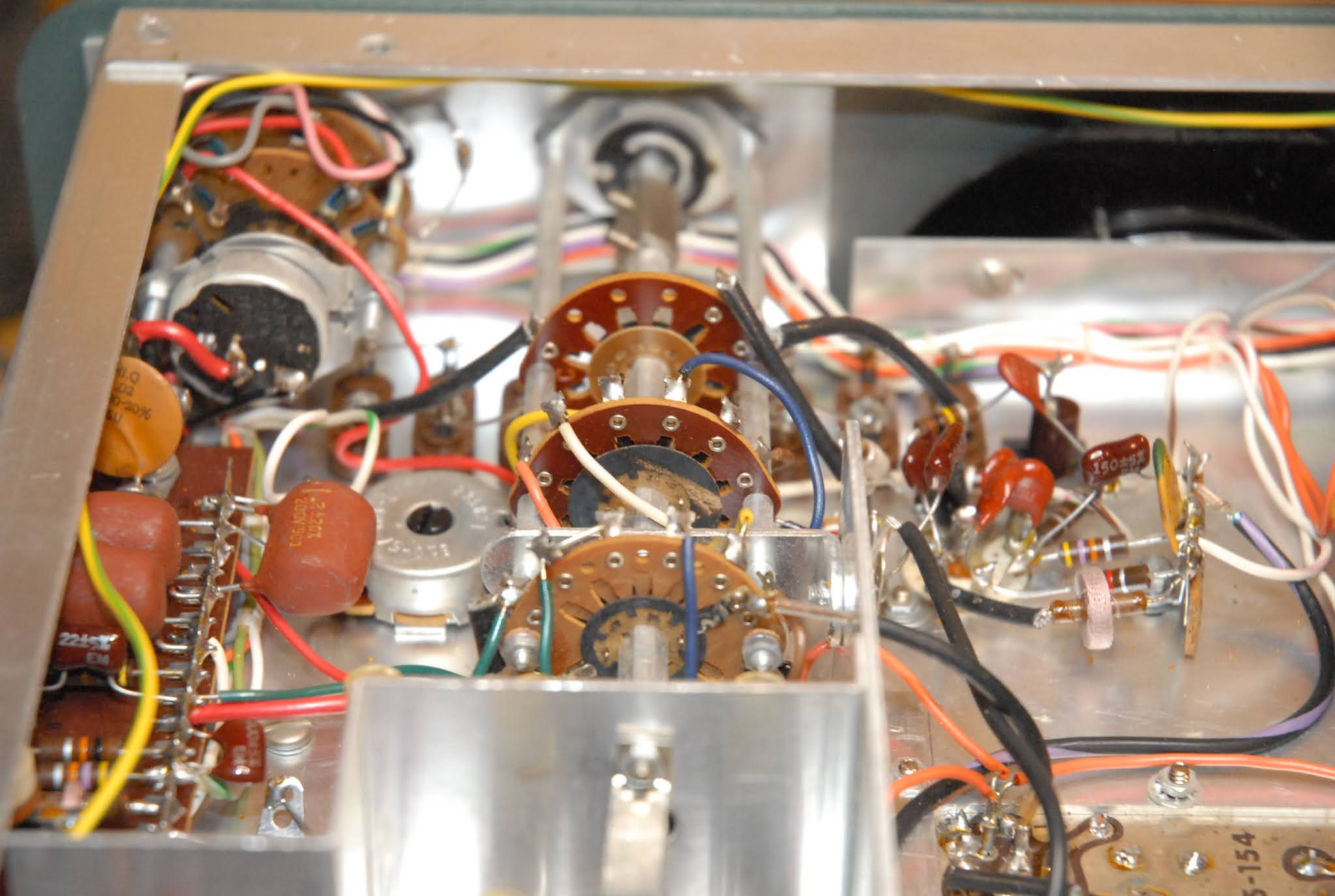
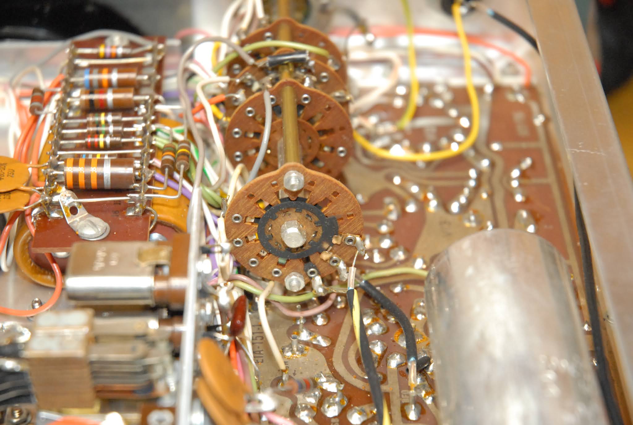
If you look closely at the second picture (click to embiggen), you can see what looks like specks of stuff on the very tarnished wafer. I don't know if this "stuff" is just dust, or some kind of crusty corrosion products. Since this radio is undisturbed, I'll get out my loupe and give it a good look.
Tribal Knowledge in the Amateur Radio Community has always held that the black Silver Oxide tarnish is just as conductive as "clean" silver, and to not worry about it on connectors and things.
But what if it's not Silver Oxide? Tarnish on Silver is composed of TWO types of Silver compounds; Silver Oxide, which Tribal Knowledge says is conductive, and Silver Sulfide, which is NOT conductive.
Short of a chemical analysis, which ain't gonna happen, I'll probably never know exactly which type of tarnish I have. And it really doesn't matter as I have a method to restore the switches back to full conductivity.
The inside of the Final Amplifier "cage" shows no signs of overheating or arcing, so that's good.

One thing I wanted to check was how tight things were around the ancient "Two Wire" line cord socket. It's a bit cozy down there, but a quick check with a scale shows I have enough room to mount a modern "Three Wire" socket to the chassis, like I did with the receiver.

I also checked the wiring around the rectifiers and filter capacitors, as this area will be getting a complete rework to replace the filter capacitors with new ones, and replace the rectifiers with 20th Century parts. The old "Bullet" rectifiers (the black 'bullets' with the yellow markings) don't have the "surge capacity" of modern ones, so every time you turn on the radio, the current surge to charge the filter capacitors puts a lot of stress on them. Better to replace them now than have one short out, possibly damaging the power transformer.
And that brings us to the only "Surprise!" item I've noticed so far.

The black rectangle in the bottom right of the picture is the power transformer. You can see the brightly colored leads coming out of the black shell of the transformer. Look closely, and you can see what appears to be some shiny stuff that looks like it leaked out.
That's the insulating tar they use in making the transformer, and it shouldn't be there. It's usually a sign that the transformer has been overheated at some point in time, the tar softened up and oozed out, and may or may not be signs of damage. If the radio was overheated due to the operating environment (very hot day in the shack, poor ventilation, running the daylights out of the radio with a high duty-cycle, etc), it might be OK. If it was due to a failing component, like a filter capacitor becoming very leaky, it would usually blow the fuse. There's a whole lotta "If's", "Maybes", and "Could Have Beens" that could cause it to happen. Since I didn't notice this until I pulled the pix off the camera and started writing this post, I can't say if it's a problem.
This is definitely the first thing I'm going to check as soon as I get back in the shop, as if the power transformer is toast (could be why the radios were pulled out of service), I'm going to have some searching to do to get a replacement.
UPDATE:
"Part 2" will address what I find.
After going over the rig again, the stuff that I first thought was tar, is actually the insulating varnish the manufacturer impregnates the assembly with. And boy, did they use a lot!
Before I flipped the rig over to investigate the bottom, I noticed the top of the transformer looked all bumpy with globs of stuff. I put my thumbnail on one of the globs to see how hard it was, and it popped off. It's clear, and very hard. Yep, seen it before and recognize it. Flipped it over, and the same stuff was what I thought was tar. It's very hard, and clear, and I broke a tiny piece off to confirm it.
And the fuse is the correct value, and looks like it's never been out of the holder before.
I'm going to say there was no overheating problem with the transformer (the varnish would have turned dark brown), but rather write it off to jumping to conclusions based on ambiguous evidence.


I'm not there doing this, but I would think that the leaking tar would render the transformer replacement as imperative. YMMV.
ReplyDeleteI'm going over it with a fine-tooth comb in just a few minutes when I go back in the shop. I have an old "Megger" I might use to Hi-Pot the transformer before I power it up.
DeleteI've seen transformers that were worse than this that lasted years, but you're right, it's definitely troubling....
I have a large amount of field experience at jumping to the wrong conclusion and then reversing.
ReplyDeleteOn the other hand, a lot of times your experience, and your knowledge have already told your subconscious the correct answer.
It's complicated.
I also noticed that the straight slot fastener of our past is almost extinct. And I think that is good.
Among the many things I learned in the the Navy was that a careful use of a hand cranked megger will wake up even the soundest of sleepers.
What threw me was that I looked at the pictures up here, instead of going back downstairs to actually look at the transformer.
DeleteWhat looked to be "Shiny Black Stuff" was actually "Shiny CLEAR stuff" on a black-painted transformer. I guess I flunked my "Photo Interpretation" class.
I'd prefer to use cross-point hardware, but I'm not swapping out that many screws.
Yes, a Megger will certainly get your attention, with even a gentle turn of the handle.
Your power supply issues make me think of the fuss people make about modern power line voltages being higher than the 50s and 60s radios were designed for. Pardon if I missed that in a prior post, but do you do anything about that?
ReplyDeleteI haven't yet because all the equipment from the 1960's I'm working with is rated for "120VAC Input". I'm not sure what I'll do if I have to lower the line voltage, which runs from 117VAC to 120VAC per my calibrated Heathkit Line Voltage Monitor.
DeleteElectric Radio magazine deals with stuff going all the way back to the 1920's, and some of those guys will fabricate a "Buck Transformer" to drop their line voltage.
I'm pretty sure you can buy units all ready to go, but I enjoy building stuff.
I think neither you, SiG or I can afford the truly NIST calibratable loads. Having worked as the engineer in a Metrology/Calibration Lab for 10 years, I know about some of the "funky" stuff that goes with calibration of RF devices. That was a fun 10 years though; I had a major hand in taking a lab from being a satellite lab to a standalone for a well known aerospace and defense company.
ReplyDeleteI don't think we need one, either. I've made small, low power loads from a resistor and a connector in a pinch.
Delete