Monday, January 31, 2022

Uh-Oh.....SLW has "The Coof"....

 Well, the test kits she got at the Safeway indicates she has it, had it, or has been exposed to it. Now considering she's "Double Vaxxed" (no boosters), and has been around The Public much more than I have, she probably has a greater chance of having been exposed to it than I do.

Or will being vaxxed show you as "exposed" to the virus?

I tested negative with the other kit she brought home, even though two weeks ago I  had a nasty cold, which I thought may have been The Plague, but apparently wasn't.

Or at least the "Made In China" test kit says it wasn't.

Thought I'd read something about these test kits being about as accurate as a coin-toss, but seeing as there are several different kits, I'm sure YMMV. We just received one of the free kits from the State of Colorado, and she says she can get three more kits for free.

Be very interesting to re-test myself with one of these kits, and see what it says....


We're supposed to get 2~4" of snow Tuesday night, and another 2~4" on Wednesday, so I get to warm up the Ariens again and drive it around. Seeing as it laughed at the 6" we had earlier, it'll be interesting to see how it handles 8".......

Thursday, January 27, 2022

RATS!! Now I'll Never Know.....

 Well, things are the workbench were going well with the Heathkit THD Analyzer, until the other night. I'd soldered two leads onto the circuit board pads that the photocell solders to, and this allowed me keep my Ohmmeter attached while I played with the position of the cell. This let me get a feel for how the cell picks up the light from the bulb, and how to position the cell. Having the shield cap off while playing likes this makes the resistance value of the cell go all over the place from room lighting, but at least I can see how moving the cell  up/down, right/left, in/out affects the reading, and could help me find the sweet spot where the cell should be.

The reading on the meter indicates 56,000 Ohms for this cell. The target is 28,000 to 32,000 Ohms, so it's wee bit off.

I moved the bulb as much as possible, and positioned the cell every which way to get a feel for it, and no matter how much I try, I cannot get it below 42,000 Ohms. The little foil reflectors I was paying with were required to even get it down that far. Now granted, I'm assuming this thing did work at one time, so what's changed?

I pulled the bulb out to examine it more closely, which revealed nothing. And then when I was putting the bulb back in, the "padded" tweezers I was using slipped, and TWANG!, the bulb goes sailing off to Where The Wild 10mm's Live......Buh-BYE!

The offending tool: 

Yes, some colorful language was used....

The replacement bulbs I'd ordered last week came in the day after, so all was not lost. These are small bulbs:

One thing I immediately noticed after I put the "replacement" bulb in place, is that the filament is about one-third the size of the OEM bulb:

And of course, it made no difference. I've checked all the voltages in the lamp driver circuit, and they're very close to what the schematic says they should be, indicating the the current flowing through the bulb is in the correct range, meaning the brightness of the bulb is probably correct. The other identical lamp driver circuit also has voltages that match the schematic, so it looks like things are working properly.

The other side with the four photocells adjusted just fine. The target resistance was not-too-difficult to get set, and adjusting them went about how I expected it should go. This leaves the one photocell as the last thing that's suspect. Looks like I'll have to go photocell shopping.....


Had about 6" of snow on Tuesday, and the Ariens took about 20 minutes from start to finish. It fired right up, and 6" of snow just disappeared. All I had to do was walk behind it and guide it, and I had to use a higher speed to keep the maw full, as it seemed to throw the snow better the more you stuffed into it. Too bad I didn't have it the last two winters!


Saturday, January 22, 2022

A Bit Of Rearranging In The Electronics Shop

 Since I've been cranking away on projects, I decided to rearrange things on the bench a bit to make it easier to use my test equipment.

I went from this mess:

To this mess:

I've been using my oscilloscope a lot on these audio projects, and this new stack also lets me integrate a new acquisition into the mix.

The newest instrument is in the second level, on the right side. It's an HP 8904A Multifunction Synthesizer. This will be used as an external modulation source for my HP 8657B RF Signal Generator, specifically for generating the FM Stereo Multiplex Composite Waveform (whew! whatta mouthful!) so I can do a complete alignment on an FM Broadcast receiver.

The old Heathkit IG-37 that I have that basically got me back to the bench Big Time is meant to do this, but I'm not really happy with how well it works. It's a 1950's design, is really touchy to get properly aligned, and has a reputation for having a high distortion level. Thew new HP will generate a very clean, very stable waveform that will modulate the RF generator. This instrument can also produce Sine, Square, Ramp, and Triangle waveforms, and will allow you to mix them, sum them, or modulate each other. It's very close to being an "Arbitrary Waveform Generator", but not as complex.

The shop/lab/dungeon is still cluttered and messy, but I'm slowly making progress on getting it organized into a proper work area. That cardboard honeycomb core door has to go, as it doesn't give me enough workspace for equipment, tools, and Unit Under Repair. I'd like to get some countertops, and make U-Shaped workbench, but I still have to come up with a frame to hold the new work surface. 


Oh, well.....It Keeps Me Out Of Bars At Night!


Thursday, January 20, 2022

Kludge or Clever?.....You Decide!

 SOOO....after I unsoldered the leads connected to the photocells, as directed to in the manual, I was able to get the photoresistors for the "Reactive" side of the bridge all set to the values listed, but the "Resistive" side of the bridge was still cranky. I went through and measured all the voltages in that section of the circuit, and they're all within tolerance per the schematic. I checked the resistors in the circuit, and they all measure within tolerance of their marked value. Everything looks "AOK", and I still can't get the photoresistor close enough to the bulb for the brightness of the bulb to lower it's value to within specs. I don't know if/how much the photresistors can drift with age, but "Bulb Aging" is a definite possibility. There's a series resistor (360 Ohms for each bulb), but  I'm hesitant to lower the value, which would make the bulb brighter, and most likely shorten it's life. Hmmmm...what to do?

I was able to track down the industry part number for the bulbs used, and they're an "1869D" bulb, still available. The range in price from Nine Dollars per bulb, to Ninety Cents per bulb, depending on vendor. I bought a couple of "10 packs" from the ninety cent guy, as it turns out they use these bulbs quite a bit in various audio oscillator circuits as part of the amplitude stabilization loop, and sure enough, the same bulbs are used in one of my Heathkit Sinewave Generators. Probably a good idea to have a few spares around here...

But in the meantime, what could I do, if anything, to make what's on-the-bench get back to where it's supposed to be?

The first thing I tried was a small piece of paper behind the bulb to position it as close as I could to the photocell (yeah, I got tired of typing the whole name), and saw some improvement.

But was it the position of the bulb, or the white paper? How's about if I try and make the most of the light the bulb produces?

I cut and bent a small piece of Aluminum foil, and wedged it in, and the value of the photocell dropped to almost in range:

So for now, it looks like by changing the size and shape of the new "reflector" in there, I should be able to get this last one adjusted to be in range. And yes, I'll tack the parts down so they don't move around and affect the adjustment.


SO, dear readers, it's up to YOU! Is this a "Kludge", a "Kluge", or a "Clever"?


As long as it works, I'll leave it "AS-IS".....


Tuesday, January 18, 2022

Olde Skool Tech.....In Action!

 AKA "I'll take Electronics I learned in Grade School for $1000, Alex!"....

Even though the copyright on the manual for this Heathkit THD Analyzer I'm restoring is dated 1978, I found a notation in ball-point on the underside of the chassis stating it was built in 1979. The actual circuit has been around "forever", and I've read in places this instrument is a virtual clone of the Hewlett-Packard 3xx series of Analyzers, as mentioned here on trona.com :

HP 331A thru 334A series (and Heath IM-5258)
These are solid-state, discrete-transistor designs; no opamps. They are Wien Bridge units with very wide range; in the HP units, up to 600kHz fundamentals(!!) and wide measuring bandwidth, above 3MHz except on the most-sensitive range. They offer low noise, and, in the 333 and 334 (and Heath unit), auto tuning. They employ average-responding metering. They have either a 400Hz passive LC high pass filter that is very good, or a passive 30kHz low pass LC filter, also very good, but not both filters. They desperately need expanded low pass filtering for better performance in the audio mid-band. Max full scale sensitivity is 0.1%, fully usable to 0.01% and below, except that their residual THD floor is around 0.01% (I've been told that the Heath has a higher floor but I've not used one). In the HP units I've used, this floor is dominated by 2nd harmonic distortion, which comes from the bridge amplifier/notch feedback system. I've never checked the depth of the fundamental null. I really should but I have good reason to believe that it is better than -90dB and may approach -100dB. Except for their high residual THD floor, and somewhat insensitive metering (300uV/0.1% full scale), the low noise and nulling of these analyzers may make them useful for measurements to 0.003% or even below.

So, looking up the HP Analyzers, we see that these are 1960's designs, all analog (or "Linear" BITD), and use very sound design principles. One of the things mentioned is that they have an "Auto Null" feature (called Auto Tuning above) that uses a servo loop to make much finer adjustments to the Wein Bridge than a human operator could. Imagine another set of tuning controls, being driven by a mechanism that can detect smaller differences than humanly possible, and tunes the other set of controls with much greater resolution than a human could.


Well, these "controls" are made of Photoresistors. Good, old Cadmium Sulphide Light Dependent Resistors, going back to at least the 1930's. They have a "Dark Resistance" of many Megohms, and a "Light Resistance" of anywhere from a few hundred Ohms to a few hundred thousand Megohms.

Think of them as a "Light Controlled Volume Control", and you're very close to having the concept.

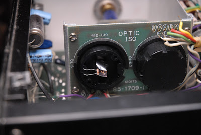
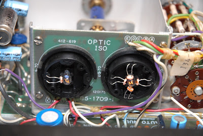
And we have five of them in the Heatkit Analyzer:

The lonely little one on the left controls the "Resistive Component" of the bridge, and the four on the right control the "Reactive Component" of the bridge. You can see the lamps glowing dimly. These normally have black plastic covers over them, but to adjust the "idling" value of them, you have to move them closer or farther away from the lamp.

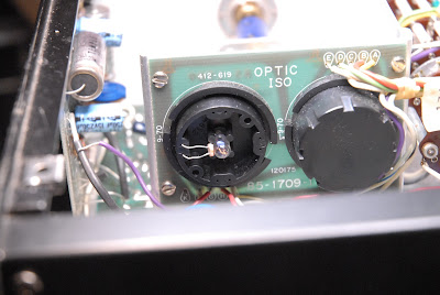
This is with the cover over the Reactive Component sensor in place:


The procedure is very tedious. Measure LDR with cover in place. If adjustment needed, remove cover and reposition the LDR. Install cover and measure LDR. If adjustment still needed, rinse, lather and repeat procedure until LDR measures the required value.

I measured them, and all were WAY off. I experimented with a couple of them, and they don't seem to want to adjust within range. Rather than freak out and order all new ones, I'm going to examine the circuit driving the lamp. They all seem to need more brightness to get down to the correct value, and that seems a little suspicious to me, so I'll do all the voltage checks of the circuits involved, and see if something is holding the lamp brightness down. I think it's a safe guess to assume these moved around a bit during the jolt the chassis received that bent up a few things.

Sunday, January 16, 2022

Heathkit IM-5258 Total Harmonic Distortion Analyzer Update

 As promised, here's the wrap-up on this section of the progress.....

The original problem was that the negative voltage regulator integrated circuit had failed, producing -30VDC instead of the -24VDC it was supposed to produce. The regulator IC is an obsolete part, and while they are available, I wasn't willing to pay the going price. Since this isn't a "Pebble Beach" restoration, I decided to use modern parts and build two individual voltage regulators, one for the positive voltage, and one for the negative. Between waiting for parts and getting distracted by other duties, it took me two weeks to get here.

The two "daughter boards" ready to be installed:

The sharp eyed will notice I reduced the size of the heatsinks compared to what I had mocked-up, showed propped up on the screwdriver handle.. The original regulators were rated at 500mA, and these are rated at 1500mA, meaning they can safely regulate three times the current the OEM parts could handle. From some looking at the specs of this thing, I figured out the circuit only draws a few hundred milliamps of current, and these should do fine with a smaller heatsink. 

So here they are all moved into their new home:

 The positive regulator has an output of 24.35VDC, and the negative regulator has an output of -24.30 volts, so they're within 50 millivolts of each other, and well within the original spec of "24 Volts +/- 1.5 Volts", which is an absurdly loose spec for an electronic  voltage "regulator".

 I left it powered up with the cover on for about 45 minutes, and my IR thermometer shows the heatsinks get up to about 120*F, while the TO-220 packages read about 103*F, so the "small" heatsinks are adequate.

So this part of the project has been completed, and I can now pick up the adjustment/calibration procedure at Step 4.  I stopped when it failed Step 3, which was to measure the regulator outputs.

Now on to exorcising the next gremlin......Yes, this is a rabbit hole I've fallen into, and I'm NOT expecting the adjustment/calibration procedure to go smoothly.


Getting this thing functional again has almost turned into a matter of pride......


Saturday, January 15, 2022

Busy, But Having Fun, Learning New Stuff, and Making Progress

 Geez....it's been a week already? Well, that's what happens when I get busy doing things instead of just blogging about them....


I spent a few days this week playing with the TEAC A-4300SX deck, as it has some bias adjustments you can make depending on what type of tape you're using, and I wanted to see if I could hear a difference between recordings made using the different settings. I have four types of tape to choose from, and I spent some time evaluating them. I have fifty 7" reels of the "Type 1" tape (standard tape, standard bias) that came with the first TEAC deck I bought. This is what most people know as "Recording Tape", and has a  reddish-brown color. The "Type 2" tapes I have (low noise, standard bias) show a definite grey tint to them, and the "Type 3" tapes (low noise, high output) and "Type 4" tapes I have (high output, high bias) are a definite dark grey color, which look just like what I was using Back In The Day.

Four types of tape, and four different settings of the bias and equalization switches on the deck gave me sixteen different recorded segments to audition. And surprise, surprise, the settings recommended by TEAC for each type of tape were spot-on.

I can't tell much difference between the Type 3 and Type 4, but they're both much better sounding than the Type 1 and Type 2 tapes I have, with better high frequency response, lower noise, and a "cleaner" sound, so I'll be getting rid of the two "lower" grades of tape, and keeping the "higher" grades I have. 


I'll post again tomorrow with some pix and updates on the Heath THD analyzer. I'm finally ready to run the calibration procedure now that I have the power supply issues sorted out.

Friday, January 7, 2022

Denver Int'l Airport Delays

 I noticed all the "racetrack" patterns on incoming flights:


I looked up one of the incoming flights, and all I found was "Delays are 35 minutes, and increasing, due to VIP movement".

Wonder who's in town??

Tuesday, January 4, 2022

Meanwhile, Back On The Workbench....

 Work continues on the Heathkit THD Analyzer. I received the rest of the needed parts yesterday, including some pieces of 1/4" Delrin rod. The Delrin is to replace a Plexiglas insulating shaft used on a tuning capacitor. Heathkit was very fond of using this plastic to make little couplings, bushings, and insulators from, but it doesn't hold up well "Over The Ages". It gets brittle, develops cracks, and eventually disintegrates, as seen below:

The "stub" on the left end should be about three times as long to engage the reduction drive for the capacitor, and the cloudy area on the right end is where the plastic cracked and split under the load from the single setscrew that held it to the capacitor shaft. Since these parts are unobtainium, I had to make one using an aluminum 1/4" shaft coupler and a small length of the Delrin rod.

This is the reduction drive, a small ball-bearing unit made in England since King Arthur's days. I remember using these back in the 1960's, and was always kind of fond of them.

And this is the fabricated replacement for the broken plastic coupling from Heathkit:

All installed and aligned:


As far as the regulators go, here's my breadboard version, built using "ugly construction" practices to see how well my resistor calculations turned out. The small IC to the left is the original regulator, and I'll connect the new ones to the holes in the circuit board where this little guy used to live.


So now that the reduction drive for the tuning capacitor is squared away, and my prototype 24VDC regulator puts out 24.2VDC, I can get back to building up and installing the two new regulators, and continue on with bringing this analyzer back to working condition....I hope!


Saturday, January 1, 2022

Ariens First Use AAR

 YOWIE! This thing works like a champ!

I cleared our driveway, our neighbor's driveway, and the sidewalks around our cul-du-sac, in about 45 minutes. The battery-powered toy snowblower I had before would take me a good hour to do just our driveway, sidewalk, and the neighbor's sidewalk down to just the corner.


And I've now formulated my "Three Laws of Snowblowing".

#1 - Clear the vehicle(s) first. Otherwise you'll wind up having to plow what you scraped off the vehicles from your formerly clean driveway.

#2 - Do the driveway second, making sure you plow out into the street a bit so SLW can get her car in and out of the driveway easier.

#3 - Do the sidewalks last.

I had been plowing one path down the driveway, then turning and doing the sidewalks, only to have to replow some of the sidewalks after clearing the driveway, then replowing the driveway after I cleared the vehicles. It occurred to me today when redoing the sidewalks for the third time that there had to be a "better" way, so the The Laws came to be, with apologies to Dr. Asimov.

I might want to check the scraper blade and skid shoe heights again as I think I can lower them maybe 1/8th inch or so to get a bit more snow off the pavement.

Other than that, it started, ran, and operated flawlessly for the entire time.


BZ, Ariens!


Meet Luna!

 Great name for our new pup, eh? She's camera shy, and "Red Eye Removal" doesn't work for dogs! She's two years old, p...