Friday, December 31, 2021

Happy New Year! along with.... Power Supplies and SNOW!

 Hope you all have a very Happy New Year this coming year. Several of "us" have had some medical issues during the past year, and hopefully those are all behind us. Several of you had surgeries, and I had some issues with my medications putting me into The Twilight Zone for a good chunk of last year.

Let's hope and pray 2022 goes better for us all.

I'm still waiting for the LM-317/337 Regulators to arrive, so I went ahead and got their new home semi-prepared. I'll be making two almost identical little board assemblies, to be mounted on the inside of the rear panel of the THD Analyzer. It's way overkill for this application, but the parts are cheap, most of them I had, and it should enable this old analyzer to continue chugging along for another fifty years.

This is what I have so far. The boards are drilled for the regulators, and mounted to the back panel to see how well they fit.


The transistors on the boards are not the regulators, but are the same "TO-220" package, so I used them for mock-up. The boards will have a couple of resistors to set the voltage, some bypass capacitors,and a few enhancements to the regulator circuit courtesy of the manufacturer's data sheets. I'll fab up a little wiring harness to carry the unregulated 35 Volts to the boards, and then carry the +/- 24 Volt regulated voltages back to the OEM Power Supply board for distribution to the other circuit boards in the analyzer.
While this is Down For Parts, I'm attending some other little "housekeeping"  items, like scrubbing all the old solder flux off the circuit boards. As Heathkits go, this one is built pretty nice, and the soldering is quite good, except that the builder used a bit too much. Considering the kit was built in 1978, I doubt the builder was using a modern, temperature-controlled, "Soldering Station", and was most likely using a "pencil" type soldering iron.

And we're getting SNOW! Supposed to get 1~3" today, and another 3~5" overnight.
 
At 1430 local:


And at 1700 local:


I'll call it 3~4", and we'll see what accumulates overnight.

Meanwhile, sleeping in the garage, and soon to be awakened....:


Took it out yesterday for a spin up and down the sidewalks and driveways. Ran it another good 30 minutes or so, and got used to the speed control, and going forward/reverse. It steers beautifully, thanks to the Ariens clutch-type differential. We'll have an AAR around this time tomorrow.

And taking advantage of a  no-work day (or two...) my son finished his birthday present:
 

 All One-Thousand, Nine-Hundred and Sixty-Nine parts, and 40" tall fully assembled.

Biggest Lego kit I've seen. Even has a Lego version of the tanks and pumps under the skin. Now all he needs is a launch tower......


Be safe out there!


Wednesday, December 29, 2021

Starting To Feel A Bit Like Indiana Jones Here.....

 Only it's not snakes, it's power supplies.

Again....

I finished cleaning up, "Buffing Out", and reassembling the THD Analyzer and started the "Initial Checks" section of the manual. 


The first few steps went fine, and then Murphy popped up again. The (nominal) 24 Volt supply measured 27 VDC, while the (nominal) -24 Volt supply measured -30 VDC.

OOOPS.....WAY out of spec

Further checking and experimenting revealed the negative supply regulator was toast, and regardless of what resistor values I used on the "Adjust" pin, the output stayed stuck at -30 VDC. The circuit uses a uA78MG for the positive side, and a uA79MG for the negative side. These are obsolete parts, and on top of that, they're in an oddball package. *IF* you can find them, they go for $20~$30 each, plus shipping. Exact matching parts, in the odd package, are available from Europe for slightly less, but the shipping is $25 for each part! Considering I only paid $75 for the whole analyzer, there's no flipping way I'm putting that much into it for two little parts.

So, I'll replace the positive regulator with an LM317, and the negative regulator with an LM337, both of which should be available for the foreseeable future. I removed the two existing regulators and their adjustment resistors, and replaced all the filter capacitors on the power supply board. I'll build up a little "daughter board" and connect it to the rebuilt power supply board, which will become the "Rectifier and Filter Board".

Cleaned up power supply board:

 Parts should be here in a couple of days, and once the new power supply is up and running I'll continue on with the Initial Adjustments and Calibration.

Our Christmas Day celebration was a joy, and we had twenty people over, including seven little ones:

Pandemonium reigned, and paper flew everywhere....


And I received one of the most touching, thoughtful, memorable Christmas gifts I've ever received:

I'd mentioned to my SLW earlier this year that I wanted to get a flag flown over the Iowa. I thought it would be nice to have one to fly on certain days. Well, she started looking into it, and found out you can get one via the Gift Shop aboard the ship. She requested it be flown on my birthday, and was told "Uhhh.....well.....we don't do special requests like that". Being the O-6 on this here base, she's used to getting what she wants, so she marched it up the chain-of-command, and through the auspices of some Friends In High Places, she was able to get the flag flown on my birthday. She then ordered a stealth raid on my Iowa memorabilia, and procured one of my challenge coins, my CPO Club membership card, and one of the BOGO coupons I still have a ton of. My son then went on eBay and found two "covers" that had been canceled aboard the ship; one from 1946, and one from the very last mail run off the ship before she was decommissioned in 1990. They put them in a shadow box, and presented it to me Christmas Eve.

I'm truly touched, and for the first time in my life, I think I understand why Military People feel the way they do when given an award. Other people deserve this more than I do, and every time I see this on the wall, I'll think of those who served on the ship, and those who gave their lives in service to their Country.

Wishing you all a very Happy and Prosperous New Year!

Friday, December 24, 2021

Christmas Eve

 And I know my audience will remember all those who are busy doing other things, and can't be home for the Holidays.

 The Kids will be over for dinner tonight, and the whole clan will be here on Christmas Day for dinner and a gift exchange.

ANNNNNNND.......I (finally) found the problem with the Heathkit IM-5248 IM Distortion Analyzer.

See this little guy marked "320K"?

It's a 1% tolerance, precision resistor, used in a section of the metering circuitry. They used a 1% resistor as this part, and another 1% resistor in a 20:1 voltage divider, to set a precise voltage for the bias level in this stage.

Only it's not 320k!

It measures 400k, a full 25% out-of-tolerance. This threw off the bias point by a similar amount, effectively killing this stage of the meter amplifier, and making it impossible to calibrate.

I'm very familiar with carbon composition resistors drifting off value with age, but this is the first time I can recall a 1% resistor going this far off the reservation.

So with this instrument calibrated and back on the shelf, I can get back to the one that "buffed out a bit" and most likely go down another rabbit hole getting that one back in service.


Tuesday, December 21, 2021

Well, It Kinda-Sorta Buffed Out....

 Used some hardwood blocks, a beefy C-Clamp, and my bazillion degree heat gun, to get this straightened out a bit.


Clamped it up:


Got it HOT, and squeezed it back:


 And it came out pretty straight:


Did a bit more tweaking, and got the small kinks out in the above picture. Also used the clamps and wood blocks on the bent rack handle, but without the heat. And yes, this one's going "down to the frame" also.


 ALL the hardware in it was loose, and with the front panel pulled for scrubbing, it makes it a lot easier to inspect and clean the switches.

This unit is back on hold, as the parts for the other analyzer arrived, and now it's back on the bench getting things replaced so I can attempt to sort out the problem(s) with the metering section. Both of these devices use the metering circuit as an integral part of the distortion measuring circuitry, so unless the metering circuit works properly, they're just door stops.


Tuesday, December 14, 2021

Uh-Oh.....This Might Not Buff Out....

 Since I'm waiting for some parts to get here to (hopefully!) fix the IM Analyzer, I decided to do a quick check on the THD Analyzer. All the capacitors in the THD (Total Harmonic Distortion) Analyzer have suitable working voltages, I have those values in stock, and they all passed the "Eyeball OK" check, I'll go with them for now.

First thing I noticed is that one of the rack handles for it is bent.


I checked the eBay listing photos again, and the handle is straight, so it must have happened in shipping. I unpacked this in the garage, and set it aside as I was busy with other stuff, so this one's on me. I thought they were cast Aluminum, but it weighs more than Aluminum would, so I guess it's a Zinc alloy, like "pot metal" or Zamak. I think if I heat it up with my big heat gun, and carefully apply pressure, I can bend it back.

The big surprise was when I pulled the covers off, and found the chassis is bent, too.

So I pulled the power transformer and the circuit boards, and see how well I can get this bent back.

 And it's another filthy unit, having been stored God knows where and for how long.


When I saw the bent chassis, I almost consigned this to the scrapyard, but since they don't come along very often, I'll try and bring it back with minimal expense, maximum elbow grease, while keeping an eye out for a replacement, like an old HP 333A analyzer:


The Heathkit is a clone of the HP, but much better built. I'd gladly take the HP over the Heath, but they tend to be a bit more expensive. Maybe I should just bite the bullet, and start looking for one.....


Sunday, December 12, 2021

Yuck.....Under The Weather A Bit and Heathkit Distortion Analyzer Progress

 Picked up a "head cold" a couple of days ago, and today was the worst. Coughing, sneezing, runny nose, and feeling like a piece of ripe elephant dung has been the Order Of The Day. At least it feels like it's breaking up and on the way out.

And the Heathkit IM Distortion Analyzer has me stumped. I know exactly where in the circuit that proper operation goes South, but I can't seem to pin down why. The DC bias voltages are within specs, if you can call "+ / - 20%" a specification. Mostly they're within 5%, which should be OK, but when I get to the second transistor in the problem section of the Meter Amplifier, they disappear. It's either something glaringly obvious,  a very subtle error, or a degraded part that I'm overlooking. This is the first Heathkit I've seen where Heath's "late-stage cost-cutting death spiral" is so painfully obvious, and I've decided to correct these built-in / designed-in flaws so I have a proper foundation. The FM Stereo Multiplex Generator had a mild case of that, where they were using a 2 Watt resistor when a 5 Watt part was called for. The resistor was dissipating 1.8 Watts during normal operation, or 90% of it's rated value. That made the resistor run hot, which made it's value drift up over the years, and completely screwed up the power supply voltages. Back when I was a cub learning these things, I was taught to NEVER use a part at more than 75% of it's rated value, and running your parts at 50% of their ratings was a sure-fire way to get a better performing, longer lasting product. And in critical cases of circuit design, you run the parts at 25% of their rated value, or less. Yes, it costs money to use a better part, and it's usually a bit larger than a lower rated one, but you've just designed-in some extra reliability.

Whoever specified the parts used in this analyzer should have been fired. The capacitors in the power supply are OK. The rectifier has an output of 75 Volts, with a 100 Volt rated part. The next part downstream is a 75 Volt part with 65 Volts on it. Tight, but probably OK. The real sore spot is that ALL of the filtering/decoupling capacitors on the "15.5 Volt" power supply rail are rated at 15 Volts. That's a huge "Don't Do It". The parts have some tolerance as to what voltage they'll fail at, and a "15 Volt" part generally won't self-destruct with 16 Volts applied to it (at least not immediately), but you simply don't run electronic components at 100% of their ratings. 

So I'm now making up a list of capacitors to order, and I'm going to "shotgun" this particular issue by replacing them all. And since the next patient on the bench is another Heathkit of the same era, I'll be taking the covers off it, and going over the schematic  to see if they did the same thing. It's more convenient to place one order than two.

Thursday, December 9, 2021

Another Three Hour Tour?

 Current project On The Bench is a Heathkit IM-5248 Intermodulation Distortion Analyzer, seen here in it's eBay listing photo:

It was listed as "Working", but with caveat "Unit may require some maintenance due to age".

All the capacitors looked and checked OK, so I began by cleaning it from top to bottom. The black bezel around the meter had a broken screw boss on the backside, and since that's how they mount the meter, the meter was shaky and wobbly. It also had a nasty scratch on the face that I polished off. I wound up pulling the front panel off to get the meter loose, so I scrubbed the bare panel. Three of the six knobs are split, and one is a mismatched knob from another Heath product. ALL the hardware on the rear panel was rusty, so it was replaced with new stainless hardware, as will be the screws holding the cabinet panels to the frame. during reassembly. All the other hardware was tightened up as most of it was loose, and the switches and controls cleaned. The AC line cord had seen better days, and was replaced.

And after doing some preliminary checks, I proceeded to begin the calibration procedure. It failed on Step 2, calibrating the AC Voltmeter. Something is messed up with voltmeter's Range switch, and when I switch to the 1 Volt range, the sensitivity disappears, and I can't get it to calibrate to match the 1 Volt RMS at 1000Hz that I'm feeding it. I've been going over the multiplier resistors soldered on the switch, and had one fall off when I wicked off the solder. That's a new one on me! Anyway, all the resistors are in the correct position, and are of the correct value. It's beginning to look like a flaky switch contact, so I'll flush the daylights out of them, and treat them again with DeoxIT.


On the bright side of things, SLW and I replaced all the grout on the kitchen counter tops and backsplash. It was really groaty looking, had chunks popping out, and was discolored everywhere. I used a 1/16" carbide tile cutting / grout removing bit in my Dremel, and a lot of patience and steady hands to grind out all the old grout that was loose and flaking away. Did several clean-up passes over all the seams, vacuumed out all the debris, and turned it over to SLW to apply the new grout. She let it cure 48 hours, and then sealed it, so we hope it will look nice for some time to come.


Tuesday, December 7, 2021

December 7th, 2021 and the Battleship Iowa is On-The-Air as NEPM


 And in commemoration of this solemn day, the US Navy has authorized the Battleship Iowa to broadcast on military frequencies using the ship's original callsign of NEPM, and listening on Amateur Radio frequencies in the 20 Meter band.

This is similar to the "Military Cross-Band Test" that gets run once a year in cooperation with the MARS people.

And because there was some spotty propagation today, I was able to finally get through and contact them for the first time since we moved here.

Kudos to the guys and gals on the Iowa for making this happen, and it marks the first time the US Navy has authorized such an operation.


Thursday, December 2, 2021

Heathkit IG-37 FM Stereo Generator and Weekly Recap

 Hope you all had a Happy Thanksgiving last week. We went to the clan's homestead way up in the canyons, did some shooting, and had a great gathering. I got to shoot a Marlin "Saddle Gun" in 45-70 Gov't, and it took a day for my shoulder to recover.  The Chevy Colorado did fine going up the "road", and I used 4WD Hi Range going up, and Lo Range coming down. Coming down you rarely exceed 20MPH, so Lo Range was fine.

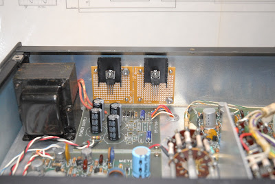
So, back to the generator. This is it after I finished it. The big shiny can on the chassis is a new power supply filter I bought from Hayseed Hamfest, one of the only places you can get new manufacture "can" type electrolytic capacitors for vintage tube equipment. They're great people, and I've been buying new cans from them for quite a while.


 And the bottom view. Some new parts visible, while the rest are OEM.


 This started out as a simple capacitor replacement, checkout, and calibration. First, I tightened all the loose hardware. And I mean all of it. It was full of loose hardware, both holding things down, and providing ground returns on the tube sockets and terminal strips. Replacing the old parts showed the soldering was not up to standards. Some things had solder globbed on them, some had cold, grainy looking connections, and three connections were barely soldered. Cleaning that up took most of a day. This in NOT one of the better assembled kits I've seen, and while it may have "worked" in 1967, it would have caused problems today.

After replacing the parts, I did the initial checks, and started the calibration. Then the problems appeared. One of the waveforms was "clipping", which meant the tube wasn't operating in it's Linear Region, and it looked to me like it was biased wrong, as only one part of the waveform showed the clipping. So, I started checking the resistor values that set the bias, and found several resistors that were out of tolerance, and replaced them. No change. I replaced several coupling capacitors between stages, as if they get leaky, and pass DC voltage, they can throw the bias voltage to the following stage off. No change, again. These are pretty simple circuits, and it was starting to drive me batty., so I dropped back to the basics, and started checking the voltages. BINGO! ALL the "B+" (aka "Plate Voltage") voltages were way off. Where there was supposed to be 134 Volts, there was 119 Volts. Where there was supposed to be 120 Volts, there was 90 Volts. The problem was in the power supply section, something I normally checked, and since I had replaced the main filter capacitor, what could be the problem? Hey, Jim! Did you check the only resistor in the power supply? Uhhhhhh....no.

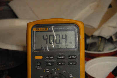
Turns out the 330 Ohm dropping resistor had increased in value to 560 Ohms, and was dropping excessive voltage. This was a 2 Watt resistor, and it was dissipating about 1.5 Watts, which is too close to it's ratings. Over the years, the heat took it's toll (common issue with Carbon Composition resistors), and it drifted high in value. I changed it out for a 5 Watt rated part, and all the voltages returned to normal. The alignment/calibration went per the book, but I don't like the way some of the adjustments acted when I was doing them. I put it back on the shelf, and I'll let it sit for a while, and redo the alignment. It might have another problem, or I might be doing it wrong.

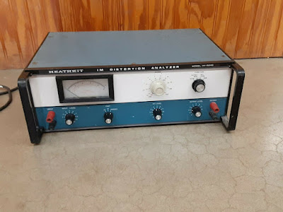
Next up was another Heathkit. an IM-5238 AC Voltmeter.

 This is all solid-state, so heat aging of the filter capacitors and other parts isn't much of an issue, and all the power supply voltages were spot-on, and looking at the DC with my scope showed no discernible ripple.

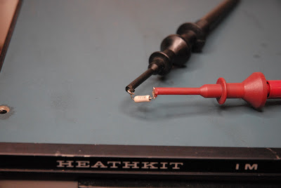
But it failed step two of the calibration. I started poking around in the circuit, flushing out the adjustment pots with alcohol, and measuring them. One of them looked "funny", so I pulled both out of the circuit board to test them. They measured to specs, so I went to put them back in. I noticed the one I was having trouble with didn't properly seat on the board, and it's leads just barely came through the board, making one connection almost impossible to properly solder. I pulled it back out, cleaned the pads on the board, and ran a small drill bit in a pin vise through the mounting holes. Mounting it back on the board allowed the leads to go through the holes all the way, and I could properly solder it to the board.

PRESTO! All the adjustments worked, and the calibration went per the book. Since calibrating this instrument requires tack soldering some jumpers in place, and this unit showed no signs of it being done, this might be a "Never Worked" kit that was built and set aside. -OR- it was soldered "just good enough" to work, and never properly calibrated. Anyway....it's fully functional, and back on the shelf.

Now to get to this pile:

This is a Low Distortion Audio Signal Generator, an Harmonic Distortion Analyzer, and an Intermodulation Distortion Analyzer. When these have been gone through I should have a nice set of audio test equipment.


Wednesday, December 1, 2021

Still Here, Just Busy

 The "Three Hour Tour" of checking out the Heathkit FM Stereo Generator so I can use it to align the Pioneer SX-980 wound up being more of a chore than I first thought. It's finished, "calibrated", and on the shelf. I just don't like the way some of the calibration adjustments acted, so I'm going to let it sit for a few days while I go through some of the other specialized audio test equipment I've picked up over the last year or so.


I'll have a post about the Three Hour Tour tomorrow. Buying used, user-assembled test equipment can be very akin to buying a "Ran When Parked" car from Craigslist. I generally assume it will need at least some of the standard things I do, like replacing all the power supply capacitors, cleaning all the controls and switches, checking the soldering, and cleaning all the dirt and grunge off the outer case, but some items need more, and I'll tell you about that next time....

Annnnd.....We Got Zip.....

 Total snow was about 6~8", but half o0f it melted as soon as it hit, and we never had more than 3" on the ground at any one time....