Thursday, January 14, 2021

SB-301 Rebuild Progress - Part 5 -

 I spent last night removing the old two-wire AC Input socket, and making way for the new three-wire socket. 

First, remove the old. This an "inside view" after I unsoldered and removed the old socket.


Then using my good friends Caliper, Nibbler, and the two File brothers, I set to work enlarging the opening from .500" x .875" to 1.2" x .875".

This is NOT something for the faint-of-heart or the mechanically inept! Taking tools in hand and removing chunks of metal from a pristine chassis like this, and not screwing it up, takes some patience and skill. As my Dad taught me, "Measure Twice, Cut Once, Or Buy A New Board!", and I've always taken that advice to heart. So, I measured about ten times, marked it out with pencil several times, held the part up to the markings, made some adjustments, took a deep breath, and cut metal.

I roughed it out with my good old Adel Nibber, and then had the File brothers attack the problem, smoothing things out the rest of the way to my pencil marks.

Yeah, I gotta be more careful to use the guidelines in the camera viewfinder to ensure the pix don't look tipped.

But, it fit!

And there was plenty of lead length on the original wires to restore the AC connections.

Drill two holes, and add hardware to finish:

One thing that's always bothered me was Heathkit's wide use of RCA Phono jacks for RF connectors. Looking at the pix of the back panel reveals a forest of them, and for RF use up to 10MHz or so they're "OK", but I always thought using them for the antenna connection was pretty cheep.

It turns out that if you remove the RCA jack, the punched hole is almost a perfect fit for a BNC connector, a "proper" RF connector.

So I swapped it out....

And no, "BNC" does NOT stand for "British Naval Connector" or any other such nonsense. It means "Bayonet Neil-Councilman", for the type of locking mechanism it uses, and the two guys that invented it.

So at this point the cleaning and replacing is done, along with resoldering several dozen connections, and cleaning up some General Workmanship Issues that would have gotten you an "F" grade in my soldering classes.

I've cleaned the workbench again, and shifted from "Repair" to "Alignment" mode, and my test gear's been warming up for about the last hour, so it's time to head back down and began the alignment process.


"Part 6" of this will either be "It's Finished", or "Awww RATS, Look What Else I found".


Stay tuned.....


Tuesday, January 12, 2021

SB-301 Rebuild Progress - Part 4 -

 So, I spent some time making sure all the dial tracking issues were solved, and then put the front panel back on the radio, taking care to align the panel as specified in the manual, as if you don't do it correctly, the dial can bind up, and things can wear out. Then I cleaned the knobs and dial bezel, polished them a bit with some "NOVUS #1" cleaner/polish, and reinstalled them.

Then I flipped the chassis over, and began inspecting all the soldered connections, and checking for "Workmanship Issues" like unclipped wires hanging through terminals, like this one on the center terminal.

And this poorly terminated coaxial cable. The ground braid goes to the third terminal from the right, and you can see all the individual strands. The soldering on the capacitor on the right end of the terminal strip wasn't too neat, so I re-did those, too.

And you can see some excess lead length through the terminals on this wafer of the VHF Converter Select switch. This, too, was corrected.


In all cases, the solder was wicked off the connection using "Solder Wick", the excess lead was wrapped around the terminal like it should have been when first assembled, and then resoldered. This is more a reliability issue than a functional one, as the connections were soldered acceptable well, but "Accepted Practice" states you wrap the lead around the terminal to make a solid mechanical connection, and then solder it. Solder has very little strength; it's just there to enhance the conductivity of the mechanical connection, and to "seal" the joint a bit. Oh, sure, we've all just "tacked" connections together to bypass a bad part, but if the assembly that tack joint is in gets  subjected to vibration or rough handling, it might very well fail and pop loose. If the device just sits on a desk it's entire life it might work for 25 years, but it's not the right way to build things.

Tomorrow's activity will be to start the process of changing the 120VAC Input Connector from an old "Two Pin" style, to a modern three pin style that uses a three-wire line cord to ground the chassis of the radio.

This will require some metal work, as the mounting holes are further apart on the new connector, and the hole for it is wider and taller. The positioning of the new connector will be such that the lettering "120 VAC" will remain, but the "INPUT" label will be gone. Small price to pay to have an easily replaceable power cord, as the two-pin style cords are now considered "Vintage" or "Antique", and the prices have shot up.

I'm also going to change out the antenna connector, from an "RCA Phono" style to a BNC female. 

I did the "Initial Tests" in the manual tonight, confirming I didn't make any mistakes rewiring the power supply. After I change out the power connector, I'll be ready to begin the alignment procedure.


Sunday, January 10, 2021

Heatkit SB-301 Rebuild Progress - Part 3 -

 As I was doing some clean-up work and just "spinning the knobs", I noticed that the main tuning knob seemed to be binding up over a segment of it's rotation, and was hard to turn at the upper end of the dial. Peeking/poking/peering into the innards as I rotated the knob, I noticed something appeared to be wobbly or misaligned, so I took a deep breath and began the disassembly of the front panel.

Off with the knobs!

Then remove the mounting hardware from the controls, and wiggly-jiggly slide the front panel assembly off the shafts.

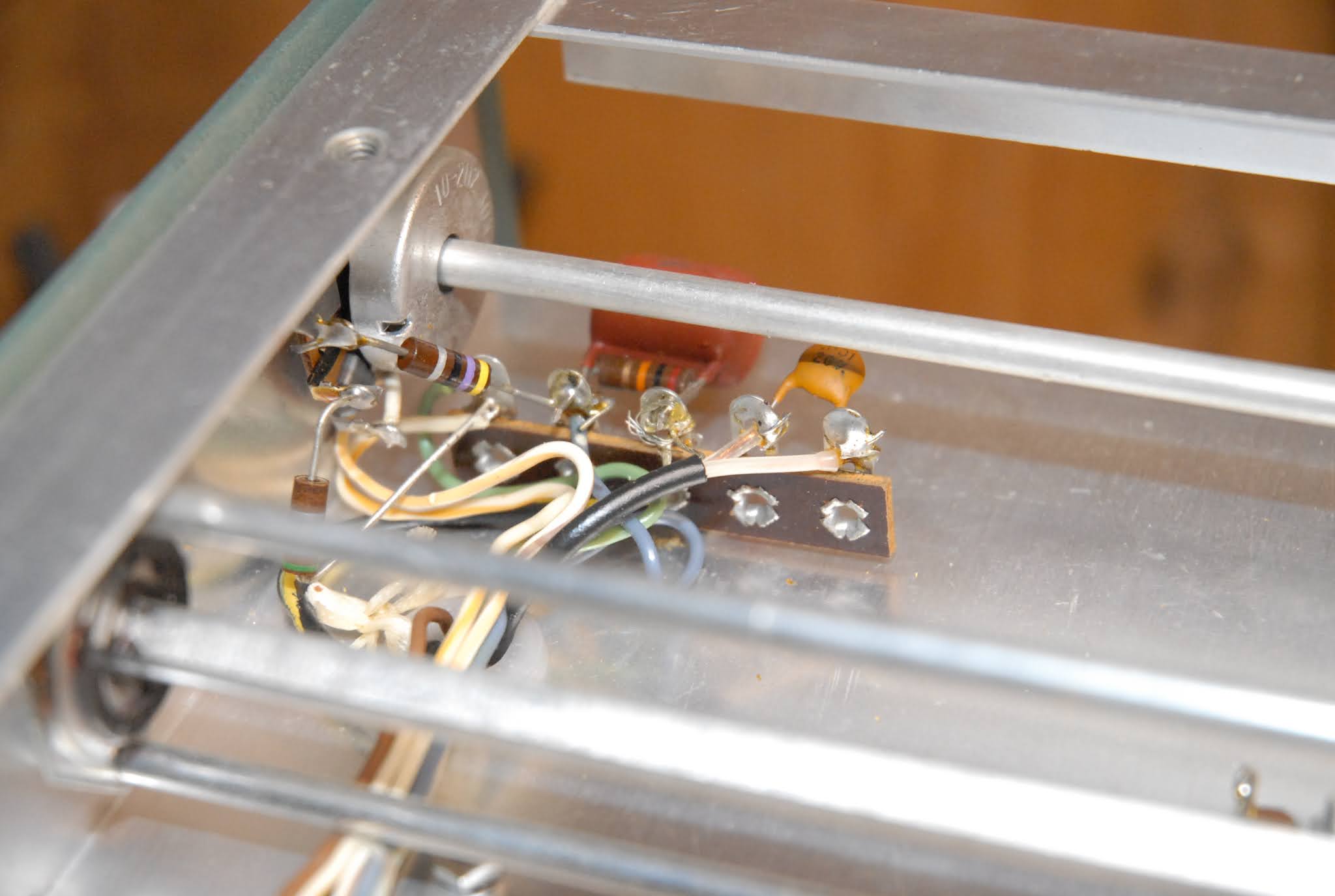
The first thing I noticed was the clear plate with the fiducial marker on it was binding on something, so I pulled the dial assembly off the tuning shaft to get a closer look.

 I took off the retaining ring and inspected the parts.

Definitely binding on something from the circular scratch marks.

Turns out the shiny metal ring that was attached to the dial itself had popped loose. It was pressed on to the dial, and had little tabs that were bent over to hold it in place. Over the years, one of the tabs loosened up, and allowed the metal ring to pop loose and move away from the dial by a bit more than the available clearance between the parts, and causing the two parts to rub together. I pushed the metal ring back into the dial, and rebent all the tabs, and now it fits flush again on the dial.

The metal ring is part of the drive assembly, and uses a "Pinch Roller" on a shaft to turn the dial. The Main Tuning knob goes on the shaft, which rotates the pinch roller, turning the numbered dial, which is attached to the tuning shaft of the LMO, the "Linear Master Oscillator", and tunes the radio.

All back together and back on the radio. The original lubricant was all dried up, so I cleaned it off and put a bit of silicone grease on it, a very good lube to use in a plastic-on-metal situation.

And I cleaned and polished the various plastic bits.

Now for the fun part, and a main reason these radios have a love/hate following.

The dial itself is marked 0-99, corresponding to 100kHz of tuning range. The LMO has five turns of range, corresponding to the 500kHz total tuning range of the LMO. 

So, have I turned the dial twice? Four times? In order to keep track of the total turns of the dial, Heath molded-in a spiral pattern into the back of the dial, which you can see through the clear plastic center of the dial. The spiral is engaged by a little nylon pin on an arm with a slot in it. You can see the arm sticking out from behind the dial, between the "0" and "95" numbers on the dial. As the dial is turned, the nylon pin follows the spiral, and moves the arm from left to right. The slot in the arm engages a pin on the back of a sliding dial pointer, which moves from 0 to 5, indicated which 100kHz section you're tuned to.

Hard to explain without better pix or a drawing, but here's the "Hundreds" marker back in place.

The love/hate part comes with getting these parts to all play nice, so the marks all line up and track properly. It wouldn't look good if the dial was on "Zero", but the sliding hundreds marker indicated "250" instead of "200", so Heath built-in some adjustments. 

The metal arm is attached to the chassis with two 6-32 screws, nuts and lockwashers. The chassis holes are slotted horizontally, while the holes in the arm assembly has them slotted vertically, allowing a two-axis freedom of movement. Getting the arm screwed down to the chassis in the correct left/right, up/down position so that the hundreds pointer agrees with the dial takes a LOT of patience, but once you've done it (a few times.....) you get the hang of it, kinda like sighting in a new scope. A little to the left, a little bit up, oops, now the zero is off so reset that, spin the knob over it's whole rotation, and rats, now the "5" is off again, and on and on. Eventually you get it to track, where the "Zero" on the dial and the major divisions of the "Hundreds" slider all match up and follow each other over the entire range, like this:


 Yeah, it's a tiny bit off on the "5", but I'm going to live with it. Took me several hours to get it this good....

And there's some slop in the dial that I don't remember from the SB-310 Shortwave version of this I restored a few years ago, so I'll look into that, but short of replacing the plastic parts in the dial mechanism, I don't think there's much I can do about it. Perhaps if I slide the dial a bit further in on the shaft, which would engage the nylon follower pin a bit deeper in the spiral groove, it might help.

And the haze on the clear hundreds marker? Well, it's on the inside of the plastic piece, and if I tried to polish it off I'm afraid the numbers would disappear, too. I've already tried gently cleaning it with plain water, and then some highly diluted soapy water, and it won't budge. I'd try some Windex, or my "Special Sauce" cleaner, but some of the Heathkit lettering is extremely easy to damage, and replacement parts only come from "Parts Radios". Fortunately, I found one on ePay, so I can swap out the clear part when it gets here.


Thursday, January 7, 2021

Heathkit SB-310 Rebuild Progress - Part 2 -

 After spending about 30 minutes reading the manual for the tube tester, it turns out I wasn't using it correctly. I didn't damage any tubes I've previously tested, but the measurements are meaningless. 

Anywhoo.....I found one tube that gave a "Merit" reading of 80%, which is the lower limit of the "Good" scale on the tester's meter. I pulled one of my new tubes from stock, and it read over 120%, as did several others from my stash. It's a 6AU6 "Sharp Cutoff Pentode", a very common tube, and there are three of them in the radio. One is used for the 100kHz crystal calibrator, a frequency reference used to calibrate the main tuning dial, and the other two are used as mixers, a type of frequency converting circuit.

With that out of the way, I pulled all the knobs off, as some of the panel bushings were loose, allowing the shaft the knob mounts on to be loose and wobbly in the panel. I also cleaned any old lubricant out, and added a drop of synthetic oil to smooth the action. I then cleaned the old lube from the detent mechanism of the rotary switches, and relubed them with some Mobil1 red synthetic grease. Then on to cleaning the potentiometers and rotary switch contacts with some DeoxIT cleaner. All the switches and controls now turn much smoother than they did before, and no more wobbly knobs!

And I tightened all the hardware on the chassis, some of which was a bit loose. Since some of these are used as tie-points to ground, retightening the hardware helps ensure I don't have any poor ground connections, which can cause noise, oscillations, and other gremlins.


Replacing the electrolytic capacitors on this radio is fairly easy. There are 4 lead-mounted capacitors under the chassis, and one large can-type mounted through the chassis.

Original parts. The three pinkish cylinders are capacitors, as it the smaller black cylinder.


Replacement parts installed.


The big can cap mounted from the topside has four terminals, and four locking tabs, and most are used as tie-points and component mounting.

It's a bit crowded in there!

The three black "bullets" with yellow lettering are the original silicon rectifiers that I'll be replacing with more reliable "modern" units. These are rated at 500V and 750mA, while the new ones are rated at 1000V and 1 Amp. They also have much better "surge" ratings, which means they're stressed less at a cold turn-on, when the capacitors draw maximum current.

Out with the old, and in with the new. You can see one of the new rectifiers installed just above the largest brown cylinder with the color stripes. It's the small, black cylinder with a silver stripe on the right end.

 I'll do some clean-up work tonight to get the solder flux bits and other loose trash out of there before I put the components back in. I'll also spend some time checking the soldering, as I found a couple of almost-cold (dull and grainy looking) connections. I also don't care for some of the workmanship by the original builder. He left some component leads longer than I would have, and a lot of them are just stuck through the lug and soldered. Proper technique should be to bend the lead around the lug before soldering, ensuring a solid mechanical connection. In some cases there was enough lead length left to do a partial wrap after I removed the solder, and in other cases there wasn't. Worst case was the lead had at least enough to make a 90* bend, which is better than just stuck-through-the-hole, but still not correct by the accepted standards in use.

At least they left a lot of length on the leads that were just stuck-though-the-hole, so once I remove the solder I can bend the excess length around the terminal or slot that it goes through, and then resolder.


This unit isn't as bad as some I've seen that made me wonder how it ever worked in the first place, but then it's not nearly as nice as others I have. It's a gamble you take whenever you buy a kit built by someone else. Sometimes the original kit builder did a beautiful job, and sometimes they didn't.

I'd give this one a B-.


Tuesday, January 5, 2021

What's On The Bench: SB-301 HF Receiver - Part 1 -

 Having gotten the downstairs Electronics Bench cleaned up, I decided to get cranked up again and get some things done after my usual mid-winter slump.


I was going to start on my Drake R4-B after spending several hours digging out my stash of Drake parts, but since I'm a bit rusty, I figured it would be better for all concerned if I started on the Heathkit SB-301 first.

Sorry for the crummy pix. Looks like my Indoor Photography skillz have tarnished a bit, too.

 Why this one? Well, a year or so before we moved here I rebuilt it's stablemate, the SB-310 Shortwave version of this, which is better than 90% identical to this one. Same tubes, same resistors and capacitors, same alignment procedure, etc. It differs only in the Heterodyne Crystals used to determine it's frequency coverage.

In other words, I've been here, and done this, so it should be easy-peasy.

And I've got out my trusty EICO 667 "Dynamic Conductance" tube tester:

 With both manuals:

Yes, I know how to "use" my tube tester, but it's way overdue that I sit down with the manuals and get to understand the tube tester. A quick check through the charts and a look at the sockets on it confirms that it will test any tube I currently use, or have in stock. I figured it would test the 6146 Power Amplifier tubes in the matching transmitter to this radio, but didn't really know until I looked at the tube listings. And a check of the front panel shows it will fit the Compactron tubes I use, and also Octal and Loctal tubes, which I don't.

And we have all the required replacement parts (less tubes) on hand:

If I need any tubes, I should have them, as I have two sets of "spares" for the SB-310. My criteria has been to reject tubes that read less than 85% on the tube tester. Is this valid? It's just something I've always done, but one of the reasons I want to RTFM for the tube tester. It has quite a good "How It Works" section, explaining how each measurement it's capable of making is made, and what the implications of the measurement are. 

So next up is to pull the tubes and read the tube tester manual while I go through them. After that I'll pull the chassis from the cabinet and clean it, and start doing things like cleaning the controls and switches, checking how well it's put together, tightening all the hardware, and doing some other basic checks to bring this back to life.


Sunday, January 3, 2021

Cinnamon Rolls, V.1 Alpha Release

 Decided to try my hand at a batch of cinnamon rolls, something I've been threatening to do for a year or so. Found an easy recipe over at the King Arthur Flower site, and set about gathering the ingredients. Almost said "chemicals" there, but hey, baking is Applied Chemistry, isn't it?

Mixed everything up, and let the dough rise.

Mistake #1 - didn't turn out the dough and grease the bowl before letting it rise in said bowl. Wasn't a huge mistake, but made it "interesting" to get it all out so I could then roll it out and butter it up.

Then cover it with brown sugar and cinnamon powder.

Getting it rolled up, and sliced into approximately equal sections, was a Charlie Foxtrot, but Sweet Little Wife helped me out, and we eventually got to here after allowing the rolls to rise about 45 minutes.

While they were rising again, I mixed up the ingredients for the cream-cheese icing.

Mistake #2 - grabbed the wrong measuring spoon, and added twice the amount of vanilla that was called for. OOOPS!

After baking for what was deemed an appropriate amount of time, at an appropriate temperature as adjusted for the altitude, we we rewarded with these.


Mistake #3 - picked the wrong combination of time and temperature. I made adjustments to the time and temp based on published guidelines for adjusting your recipes to a 5000' altitude, and my bread baking, which confirmed the guidelines.

In short, you increase the temperature and decrease the time to avoid drying out your bread.

Guess what? This ain't bread. It's pastry dough, and bakes differently than just a straight yeast bread does. The extra butter and eggs change the chemicals enough to make the reaction go in an unexpected way. In this case, while the outside 2/3 of the roll is completely cooked, the inside 1/3 "core" of the roll isn't fully cooked. It never developed into the nice, light, almost flaky crust a Good Cinnamon Roll has through-and-through. They're not raw, just not fully cooked, and a bit doughy. They taste pretty good otherwise, although the icing has a bit too much vanilla for my taste.

Next time I'll make sure to use the recommended 400* oven, and let the time run the full 15 minutes. We took the pan out once to inspect the bottom, and it looked like the sugar was caramelizing nicely, but we just flat took it out too early, based on the rolls looking "Golden Brown". The higher temp got the outsides done just fine, but the shorter time didn't allow the heat to fully penetrate the denser dough and completely cook it.


Thursday, December 31, 2020

Happy New Year, and Carving Almost Complete

 SOOOoooo....here we are, which is most likely not where we'd thought we'd be. A staged pandemic, an election with absolutely breathtaking amounts of fraud, and economy in shambles, and all the other stuff I can't be bothered mentioning, but we endured.

Yes, "endured".

No, it's not The Great Depression or a World War. Those may be Coming Soon To A Former Republic Near YOU!, but it's still not 100% decided. I don't know what's coming up this year, but I don't think it's going to be "pretty", for given definitions of "pretty".

So take care, keep your head on a swivel and your powder dry, and we'll see what comes.


On to more mundane matters....

Trevor The Tree Carver has been busy since the last update. He's just about finished, and has only some final detailing, sealing, and clean-up to do. It should look quite nice this summer.


Awwwww....RATS! Booger uploaded my pix in the reverse order I selected them in.

And I'm too lazy tonight to correct it.

A fitting end for 2020! Think I'll be down in The Bunker with a portable radio until 2020 is out of here.....

Monday, December 28, 2020

A Bit More Tree Carving....

 Took this today after Trevor left due to blowing snow!


He's been working on the trunk, turning it into a stack of boulders with roots growing down through them. The baby owl on the small limb was supposed to be a squirrel, but as he carved away the wood, a crack in the limb started to open up, and he was afraid it would break apart in a few months, so he cut the limb back, and carved the owl.

Should be pretty impressive when he's finished carving it, burning in more detail, and sealing it.

Sunday, December 27, 2020

Tree Carving Resumes....

 At least for today and tomorrow.

Trevor is almost finished, and the next few days will be devoted to finishing it up, burning in some details, and then slathering the whole tree in boiled linseed oil to seal and preserve the wood.


The new figure is another owl. He started roughing in a squirrel, was a pretty far along on it, and the trunk split along a line he was worried about. So, we another owl instead of a squirrel.


Christmas Eve aftermath.....


Yes, the wrapping paper has been stuffed in a bag, or we'd be waist-deep in it!


We Hit 'Em.......<i>Now What Happens?</i>

  Breaking story from Newsmax.....