Thursday, January 17, 2019

Speaker "Kits" Arrived Today

And calling these things "kits" is being overly generous.

Calling them "semi-kits" would be more accurate, but even that's a stretch.


Nope, this is a collection of parts, packed in a box, and shipped out.


And why, pray tell, are power tools and hole saws on the bench with right out-of-the-box speaker "kits"?


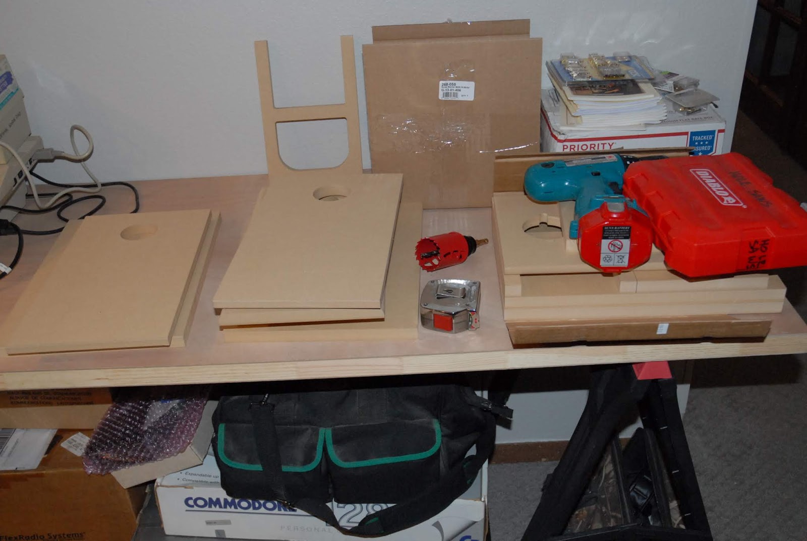
Why because they didn't give you any way to connect the assembled speaker to the stereo! I suppose I could have drilled a small hole, and run a few feet of wire out, but what then? No, you need an Interface Connector to handle that function. Since the output connectors on most real stereos are some form of a "5-Way" Binding Post that accepts banana plugs, having matching connectors on the speaker is the way to go. So, drill a 2" hole with the hole saw, and mount these nice little "5-Way" Binding Posts plates in the new holes.

Screws not included, of course.


After drilling, just press-fit in the hole.


Might as well do both at once while I have the tools out.....


The pre-made hole in the back panel of the speaker is for the "Tuned Port", a deliberately sized "air leak" in the box that lowers it's Resonant Frequency, which increases the lower (Bass) frequencies the speaker can reproduce.


Mocking them up sans glue.....


And here they are with the side panels and stiffening baffle glued in and lightly clamped.


I'm not a cabinet maker, and never pretended to be one, so I have to say these 3/4" thick, MDF, "CNC Cut" pieces fit together beautifully! After a 24-hour glue curing time, I'll fit the two remaining pieces, and glue them in. The front doesn't get glued on until the very last, and I'm thinking of maybe screwing it on with a thin gasket in there.


The enclosures get lined with acoustic foam to subdue high frequencies inside the box (makes the treble less "harsh"), and the cross-over assemblies have to be built.

No circuit board provided, of course.

Then the speakers get screwed into the front panel with the screws that were not included with the "kit", and the two speakers get wired to the cross-over network, and the input to the cross-over network gets wired to the nifty little Interface Connector I installed on the back, guess who supplies the wire, and the front gets mounted (somehow), and they should be ready to play.

Rather than leave these naked MDF, I'm going to coat them with something like bed liner that Parts Express sells. It's water-based, so the odor won't drive you out while it's curing, and it's extremely durable. I'll sand them out before I do it, and come up with some way to make the front removable.

Oh, and I've had to order about $50 in additional parts (so far) to build my "kit" speakers.

Wednesday, January 16, 2019

Vintage (Ancient?) Home Computing

Had to clear off the "workbench" on the other side of the room I use for my downstairs workshop so I can build the speaker kits when they get here.

After the bench was cleaned off, it looked a bit too empty, and I had these boxes stacked under it, and I really wanted to see if this stuff still worked, and.........

An hour later (had to find all the cables) I had my Commodore 128 set up and running "VR85", a satellite tracking program.


Three of the four disk drives I have appear to have developed problems. Two of them act like the AC power socket is intermittent, and one of them has a problem with release lever not working. Sigh......more stuff to fix....


Anyway, now that the C=128 itself appears to work OK, and the monitor is clear and sharp, the plans for this computer include getting it on Packet Radio with my "A&A Engineering" DigiCom64 modem (right) and DigiCom64 program cartridge (left).

This is the gear I used when I used to contact the Hams on the MIR Space Station. I had just gotten back into Amateur Radio a year before, and had moved in to a really cool bachelor apartment in a large two-story commercial building. The landlady let me put up antennas, and I was off and running! Didn't have much disposable income, so I had to get pretty creative in assembling a station. I had an old, beat-up Alinco DR-590 that I pieced together from several junkers, and an Antenna Specialists 2 Meter vertical that somebody gave me that needed to be disassembled, cleaned, and reassembled to get all the corrosion off it. I used the radio on simplex and repeaters for voice work, and by unplugging the microphone, and plugging in some adapter cables to connect it to the modem, I used the same radio with the Commodore on Packet.

This is a "spare" modem in the picture as I can't locate my original one, but the cartridge is the same one I used on packet back in the middle 1990's, before cheap Internet came along and pretty much killed off Amateur Packet Radio.


Since the Commodore can't multitask (i.e. run more than one program at a time) I had to run the tracking program to see what satellites would be visible, and when, and print out the pass predictions, then load the DigiCom64 Packet Radio software and make ready the radio for digital operation. It worked a treat, and what looks ancient, archaic, and obsolete today was actually not that many years out of the "state-of-the-art" category at the time.

And it was CHEAP! I got the C=128, two disk drives, and the monitor for $40 from a friend. The tracking program was $15, the packet modem was $65, the radio and antenna were FREE, and I had about another $75 in cable (most of that cost was new feedline for the antenna), connectors, and misc stuff.

For less than $200 I had a complete "2 Meter/440" station that I could use on voice, packet, and track satellites with. Pretty sweet at the time.

And 'ya just gotta love those 8-bit graphics!


Thursday, January 10, 2019

Speaker Choices.....

With the rebuild of the Heathkit proceeding apace, I'll need to get some real speakers for it. I have some "P.A. Type" speakers (carpet covered, 8" woofer and a dome tweeter) that I could use, and some Radio Shack/Realistic/RCA "Optimus" mini-bookshelf speakers, but the P.A. speakers aren't really for music (no top or bottom end; all tailored for voice), and I could easily turn the little Optimus speakers into smoking ruins with the Heathkit. Since the amplifier section of this receiver is known for being less than 100% stable with 4 Ohm speakers of current design, and 16 Ohm speakers aren't very common, that leaves me with 8 Ohms as the 'load impedance of choice'.

The amp section is rated at 75 Watts-per-channel with the "Institute for High Fidelity measurement method", and that translates to about 55 Watts RMS, which is much closer to "Real World" than the IHF method. Some of the methods used to measure the power output of an audio amplifier are quite....uh....."creative", and were devised to inflate the RMS power measurement for advertising purposes. I used to chuckle when I read some of the results, as they were grossly higher than what the thing would actually put out.

So, I need some 8-Ohm speakers, rated for around 100 Watts. You can easily spend $2k per speaker, something I'd never do unless that rich Uncle I don't know about kicks and leaves me a few semis full of cash.

So after receiving a $25 discount code from Parts Express, I pulled the trigger and ordered two "Hitmaker MT" speaker kits, along with some bits (like binding posts to connect them!) needed to finish the kits.

They should be here in a week or so, and I'll report on them when they get here.

And since it's going to be raining/sleeting/snowing on Friday, I put the BuddiPole vertical back up. The winds have died down for the present, so it's safe to get it back up in the air.

Tuesday, January 8, 2019

Heathkit AR-15 Progress

Been chugging along on the Capacitor Replacement Train here for the last week, and as of tonight, all fifty-four of the printed circuit board mounted electrolytic capacitors have been replaced.

These boards are (from left-to-right) the Multiplex Board, which handles the special process of reconstructing separate left and right channels out of  what's broadcast, then two identical Power Amplifier Driver Boards, which take the selected audio stream and amplify it enough to drive the four power transistors mounted on the heat sinks. Above those two boards is the Power Supply Board. This board provides mounting space for the main power rectifiers, as well as the circuitry for several other regulated supplies.

The circuit board with all the control shafts jutting into free space at the top of the picture is the Control/Preamplifier Board, which selects the input you want (Phono, Tuner, Tape, Aux), processes the audio for Bass, Treble, Balance, and Volume, and then sends it to the Power Amplifier Driver Boards.


In the picture below you can see how all the pots (potentiometer) the shafts are connected to are soldered onto the Control/Preamplifier Board. I wound up having to take this thing a lot further apart than I wanted to, but it was the only way to get enough access to the Control/Preamplifier Board. At least it gives me a chance to clean both sides of the dial glass!


This is the "top" of the component side of that board, as seen looking towards where the front panel normally is, with the old caps in place.


And this is the "bottom" of the component side with the new caps installed.


Besides replacing the caps, I cleaned all seventeen controls, the Input Select rotary switch, three slide switches, and seven rocker switches. Some of the controls I could only get at from the top, and the rest I could only get from the bottom, so cleaning them was a multi-day affair, depending on what side of the chassis I was working on.

On the Tuner Board, I replaced all the electrolytic caps, and cleaned and lubed the bearings in the tuning capacitors. The two rectangular grey boxes are 10.7MHz crystal filters. These give this receiver razor-sharp tuning, even in crowded Metro areas with 50kW stations all over the place.


And I disassembled the heatsinks, cleaned them to get all the old silicone grease off, and them reassembled them with new thermal pads instead of using mica washers and grease. That's a new 3-wire grounded AC cord temporarily strapped to the chassis.


After doing these heinous things to this old war horse of a receiver, I rounded up the usual suspects to interrogate them.


As expected, they knew nothing....Off to the landfill with them! I've seen used parts like this for sale on eBay. Seems people are looking to reproduce "Vintage Tone", and as all the Audiofools know, you need Vintage Parts to get Vintage Tone! Seriously.......

Now I'm In Work coming up with some mounting bracket to use with the replacement power supply filter. The OEM cap was 8,000uF @ 90VDC, and even though the new one is 10,000uF @ 100VDC, it's considerably small in diameter; 2" vs 3".


So even though she's a stripped-down hulk right now, work is progressing, and I'm looking forward to doing the alignment on it with my new test gear.


Have fun, be safe, and Carry On!

Monday, January 7, 2019

Windy!

Been running right around 35~40MPH sustained, with (predicted) gusts to 65~70MPH.

Be careful out there, especially if you're out on the highways.

Saturday, January 5, 2019

Workshop Adventures

Since it's been too blasted COLD to do much out in the garage, I turned my attention "inward", and spent a bunch of time this last week down in The Dungeon, a.k.a. the basement.

I went through all my bookshelves and cleaned them up, sorted them, and found 45 books that I no longer have need of, mostly "prepper" and "Post Apocalypse" type books. Those will be going to one of the numerous second-hand bookstores we have in town. I'd rather give them to a book reseller and have them make a few $$ on them than toss them in the recycling bin.

And removing those books freed up two complete shelves for other use.

Then I turned my attention to the little Krohn-Hite Function Generator that was sitting on the shelf awaiting repair.


It's a decent generator, but had a problem (I thought) with the negative power supply.


I replaced both electrolytic capacitors, both 75 Ohm current-limiting resistors, both transistors, the blackened Tantalum capacitor that got cooked by the burning resistor, and added new heatsinks with some thermal grease to keep the transistors cooler.


And along the way, I found a "repair" done very sloppily by someone in the past. The soldering was OK, but to not clip the leads on the new parts you just installed is pretty poor workmanship!


After I was done, I checked the negative and positive power supply lines for shorts, and RATS! There's still a 3.2 Ohm short on the negative supply, probably what took out the parts I just replaced. One thing I noticed was one of the other Tantalum capacitors had gotten hot enough to melt the wax on a ceramic cap, so I replaced that cap, but no joy.
 

One of the "Old Radio" forums I frequent had a repair thread about this generator, and consensus is that either the 741 Op Amps used as error amps in the supply are bad, or another of the numerous Tantalum caps on the negative supply line are shorted. I have some 741's, so when I get another round tuit, I'll swap those out. If that doesn't fix it, I'll start lifting component leads on the negative supply until I find the failed part.


So the little Kron-Hite went back on the shelf, and I dug into my HP 8601A RF Sweeper.


The crank knob to set the frequency was really stiff and hard to turn, so I had to do a bit of fettling on it, cleaning the old grease out, and relubed it with some synthetic gun grease I had. The freq adjust knob now spins freely, but yow....this thing is WAY off in calibration. I mean like EIGHT MHz off from what the dial displays compared to what my counter and spectrum analyzer read. Since I have the manual, I started running the performance checks, only to run into a wall because I don't have any SMC connector adaptors so I can connect my spectrum analyzer to the connectors on this module:


And then peak the little 200 MHz Reference Oscillator coil, which is the white tubular component in the picture below.


So the HP RF Sweeper is also back on the shelf until the adaptors get here so I can make the measurements.


And the capacitors for my Heathkit AR-15 arrived from Mouser.


Here's a before shot of the power supply and power amplifier driver boards with the "As Built" capacitors installed:


And here's the after shot with the new parts installed:


Leaving me with a rapidly filling bag of OEM capacitors.


Some of the new capacitors are smaller in physical size than the old ones, but with increased ratings, and some are the same size as the originals, but with greatly increased ratings.

I also bought new thermal pads for the TO-3 case transistors. The "As Built" configuration uses mica washers with silicone thermal grease. While this was accepted practice in the late 1960's when this receiver was built, technology has advanced, and the new parts are cleaner, easier to install, and have comparable heat transfer characteristics to the old system.

Tonight I'll replace all the caps on the Tuner Board, the Phono Input Board, and get started on the Multiplex Board. I wasn't careful when I had the bottom cover off, and when I was wrestling this 25 pound lump around on the bench, my thumb hit one of the filter inductors on the Multiplex Board, and snapped it. It's made of phenolic, kind of like wrapped paper dipped in varnish, and after 50 years was pretty brittle.


I haven't decided if I'll fix it in place, or remove it from the board to repair. I'll see how robustly it's mounted to the board tonight as I'm working on other sections.

I'm just getting rolling on this receiver, and it'll be interesting to see how it turns out. I'm going to need some decent speakers for it, and Parts Express has some nice kits for reasonable prices, so it looks like I'll be ordering one of them soon.

Monday, December 31, 2018

Happy New Year!

It's 13* and snowing, with an expected low tonight of -3*.

We're staying in, as temps under 10* don't agree with us.

"There Was A Time...." when I would have been out hootin' and hollerin' on New Years Eve, but now I'd rather stay in, let the youngsters do the hootin' and hollerin', and tinker away on something.

Be careful if you're out and about tonight. There were many time I shouldn't have been driving, but did anyway, so watch out for the other guy.

Friday, December 28, 2018

What's On The Workbench?

Had a couple of "small" projects I knocked out before going into my next "big" project.

The first was the installation of an LED light kit for my Yaesu rotor control head. The OEM incandescent bulb is a non-serviceable part, and one of the cottage-industry Ham guys came up with a  nice little PCB with three white LED's on it. Took about 30 minutes to install it, it's much brighter, and will probably never "burn out".

The second project was rebuilding my #2 Drake MS-4 speaker with AC4 power supply. The original speaker is old and dried-out, and the electrolytic capacitors and rectifier diodes in the power supply are old tech, and better modern components are available.


In the same space, you can now have capacitors with higher voltage ratings (good for reliability), and more capacitance (better filtering), with a higher temperature rating (better reliability again), and better manufacturing processes. The rectifiers also have higher voltage and current ratings, and their surge capability is far higher than the old type rectifiers the supply was manufactured with. And all the new components mount on a convenient PC Board.


The supply looked like it got into a bar fight at some point in it's life, but since this is an aluminum cover, I should be able to make most of the dents go away.


Pretty clean inside, though....


But, yow....I haven't seen rectifiers in a "Bullet Case" package since high-school! These are 1N3194's, rated at 400V and 750mA. The replacements are rated at 1000V and 1A, a nice upgrade.


So most of the old capacitors, and all of the rectifiers get removed. The two big can capacitors were left on 'for looks'.


Then the new PCB gets mounted, wired in, and a couple of cable ties added to keep the wiring neat.


And the speaker gets replaced.....


Testing revealed 790VDC no-load on the HV, and 275VDC on the B+. Bias (for the 6DQ5 final PA tubes) is adjustable from -25VDC to -65VDC, all well within specs.

So bolt it all back together, and put it back on the shelf next to the one I did a few weeks ago.


Yes, they're sitting quite differently. The one on the right has the "short feet" on the back of the enclosure, tilting the panel back slightly, while the one on the right has same size feet, making it sit level.

Next up on the project list.....my Heathkit AR-15, soon (actually already is) to be On The Bench.


We Hit 'Em.......<i>Now What Happens?</i>

  Breaking story from Newsmax.....