As promised, here's the wrap-up on this section of the progress.....
The original problem was that the negative voltage regulator integrated circuit had failed, producing -30VDC instead of the -24VDC it was supposed to produce. The regulator IC is an obsolete part, and while they are available, I wasn't willing to pay the going price. Since this isn't a "Pebble Beach" restoration, I decided to use modern parts and build two individual voltage regulators, one for the positive voltage, and one for the negative. Between waiting for parts and getting distracted by other duties, it took me two weeks to get here.
The two "daughter boards" ready to be installed:
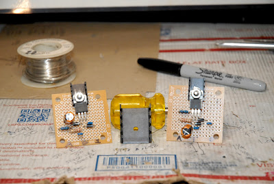
The sharp eyed will notice I reduced the size of the heatsinks compared to what I had mocked-up, showed propped up on the screwdriver handle.. The original regulators were rated at 500mA, and these are rated at 1500mA, meaning they can safely regulate three times the current the OEM parts could handle. From some looking at the specs of this thing, I figured out the circuit only draws a few hundred milliamps of current, and these should do fine with a smaller heatsink.
So here they are all moved into their new home:
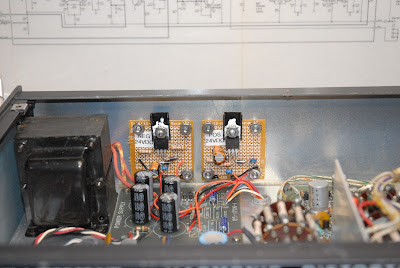
The positive regulator has an output of 24.35VDC, and the negative regulator has an output of -24.30 volts, so they're within 50 millivolts of each other, and well within the original spec of "24 Volts +/- 1.5 Volts", which is an absurdly loose spec for an electronic voltage "regulator".
I left it powered up with the cover on for about 45 minutes, and my IR thermometer shows the heatsinks get up to about 120*F, while the TO-220 packages read about 103*F, so the "small" heatsinks are adequate.
So this part of the project has been completed, and I can now pick up the adjustment/calibration procedure at Step 4. I stopped when it failed Step 3, which was to measure the regulator outputs.
Now on to exorcising the next gremlin......Yes, this is a rabbit hole I've fallen into, and I'm NOT expecting the adjustment/calibration procedure to go smoothly.
Getting this thing functional again has almost turned into a matter of pride......

Carry on, my good sir. I take immense pleasure in watching your progress, and wishing I had learned more of the skills you possess.
ReplyDeleteAs I joke with my SLW...."It Keeps Me Out Of Bars At Night"!
DeleteBeen building things like this since I was a kid, but we didn't have IC's. The best I could have done Back Then would have been to use a Zener Diode and a Pass Transistor. These little champs are much tidier!
"It Keeps Me Out Of Bars At Night"
DeleteThe cars my friends and I bought as teens were more projects than reliable transportation. I remember a parental comment about our cars keeping us off the streets. True in more ways than one...
Same here!
DeleteThe regulators are a very cool homebrew project. I am vicariously enjoying your restorations. And you *should* be proud.
ReplyDeleteThanks, Bob!
DeleteDid a quick check last night, and it (again!) fails the very next step in the adjustment/calibration procedure. It calls to measure the collector voltage on a transistor, and set the Bias Adjust pot to indicate 7 Volts. I noticed the pot was already set to the far end of it's travel, which corresponds to 7.5 Volts, so time to start poking around in there.
It's kind of ironic because the problem is in the Meter Amplifier section, the same section on the other instrument the gave me fits for a week.
Murphy Lives!!
Nicely done!
ReplyDeleteThanks, NFO!
DeleteNow I'm chasing down the problem on one of the five circuit boards in it.