Friday, February 12, 2021

Holy Moly, it's COLD!

 3.8* @ 2130 here, forecast to drop to -6*, and there's some flakes coming down.

It's not as cold as some places are reporting, but it's the coldest it's been this season, and we've got 2~4" of snow on the way.

Finally got the new 3-wire AC input socket installed on the SB-401 transmitter. It might look like it's not-quite-straight in the chassis, but it's not tightened down yet.

 Over the last week, I've built and installed three new media storage racks, and sorted out four U-Haul boxes of CD's and DVD's, and got them pretty much organized.

The lighter colored rack to the left is SLW's collection, properly arraigned alphabetically, and the two black ones on either side of the doorway are all of mine, arranged by genre.

This area was previously stacked with boxes and packing material, and now all the boxes have been flattened for easier storage, and the packing materials stored separately. I still have a ton of stuff to get rid of, and the boxes will get recycled to ship things in.

The area under the model car workbench was also stacked with boxes, and those have been taken care of, too. The bench will get cleaned up as the weather warms, and I can run the little cars outside again.


Plans for the weekend include hunkering down, having a fire, and watching a movie. TLG won't be here until Tuesday, as his Mommy and Daddy have a 3-day weekend together. BTW......the DIL is expecting again, with an August 20 due date. Fingers-crossed and prayers sent that she has an easier time, and goes full-term.

Friday, February 5, 2021

Friday Already?

 Geez, I should get out more often!

Had some "Bumps and Lumps and Down In the Dumps" the last week, so rather than work more on the transmitter (I did get the new AC socket installed), I decided to work on cleaning up the "Storage Room" in the basement. Found some things I haven't seen since we moved here, and started sorting stuff out.

I now have another huge box of clothing to donate to our local ARC Thrift Store, several boxes of electronic "stuff" have been reduced to one box, and I have a whole bunch of somewhat rare, obscure T-Shirts to sort through from my rocket chucking days. I'm only going to keep the ones with the best graphics, and that means those with just the name of the satellite or mission name on them will be hitting ePay for disposal. I have more than enough plain, white T-Shirts with obscure logos where a pocket should be, and I don't need more. If they don't sell, they'll go to the Thrift Store.

And I dug out all the APC UPS units I have, and will probably put them on the "Come And Get It!" email list the local Ham Radio Club has. I kept the two with the newest batteries plugged in since we moved here, but they all should have new batteries installed. 

I gave away a Systron-Donner 1702 Signal Generator and a Tektronix 492 Spectrum Analyzer I posted on the list last week, and that opened up some floor space, and now with the UPS units moved out, I freed up some more. 

Now there's plenty of room for Pebbles' dog bed in the shop, and I'm sure she'll appreciate it.

Monday, February 1, 2021

SB-401 Transmitter Rebuild Progress - Part 6 -

 In which I joyously announce all the switch contacts are cleaned!


 I have no idea why I took that picture, when the switch to the right of it shows a whole row of cleaned contacts to impress you with. Oh, well...

And all the rotary controls have been cleaned and lubricated, and more glaring examples of Poor Workmanship have been corrected.

And I started on the next item on the punch list, updating the AC Input connector. I removed the original connector, and penciled-in the cut-lines for the new one.

After I get the new connector installed, I'll start moving on to the Power Supplies in the radio. All new manufacture filter caps will be installed, followed by new rectifier diodes with higher ratings. The original diodes were rated 750 Volts PIV and 750mA Forward Current, while the replacements are rated at 1000 Volts PIV, and 3 Amps forward current. A bit overkill on the current ratings, but I have good supply of 1N5408 diodes from the little place back in Torrance I used to get items like that from.

And it's forecast to be sunny and in the low 60's tomorrow. Probably ought to get Sweet Little Wife's snow tires on. I think we're gonna have a slushy/snowy rest-of-the-winter.


Friday, January 29, 2021

SB-401 Transmitter Rebuild Progress - Part 5 -

 In which Murphy walks in the shop, dumps over my coffee, and laughs......

Well, I hit a snag in the process of removing the knobs on the control panel so I can free the control panel from the chassis, and repair the dial mechanism. It's an identical procedure to what I did on the receiver, but this time one of the knobs fought me. It uses a small, Allen-drive setscrew to secure it on the shaft. It takes an .050" Allen wrench to get it loose. And the setscrew is in an awkward position, meaning it's hard to get the teeny-tiny Allen wrench all the way into the setscrew to tighten and loosen it. Most people don't get the wrench fully bottomed out, and they round the corners of the wrench, and round the corners of the setscrew, meaning it gets very difficult to get the setscrew loose.

I tried brand-new wrenches with sharp corners, grinding an older wrench so the rounded off part was removed, heating the metal insert the setscrew threads into, and lots of other things, including turning the knob a bit too hard.........POP!....there goes the coffee....

I broke the little "paddle" off the knob by pushing on it with my thumb, and it shot off across the shop towards The Place Where 10mm Sockets Go To Die......

The bright green color is where the "paddle" that hangs down used to go. So now I HAVE to get the knob off so I can replace it. I was able to easily cut off the green plastic, and then attacked the aluminum insert the setscrew threads into.

Took a good 90 minutes of gently cutting away parts of the aluminum insert so I could "split" it, release the tension provided by the setscrew, and slide it off the shaft.

You can see the setscrew sitting there laughing at me....

So finally, and with minimal collateral damage, I got the insert off the shaft.

In other news, The Brown Truck of Happiness stopped by today with a load of Thermionic Devices of types I didn't have, so at least some things are progressing.

Too bad we can't "Reload" tubes when they get used up.


Enjoy your weekend!


Tuesday, January 26, 2021

SB-401 Transmitter Rebuild Progress - Part 4 -

 Got the new BNC connector all squared away, and replaced the mismatched hardware on the SO-239 RF Output connector. Still waiting on parts because I can't locate a couple I thought I had.

So I went on to my favorite pastime lately, cleaning wafer switches.

This is the Function Switch, all cleaned and lubed.

Before I got started cleaning the switches, I went through the whole chassis tightening hardware. Seems like every time I put a screwdriver or 1/4" nut driver on a piece of hardware, it was loose. Sometimes maybe an 1/8th of a turn, usually about 1/4 turn loose, and a couple that were over a full turn loose, which is definitely in the "Finger Tight" category. Since most of these either grounded the periphery of a printed circuit board, or were securing a ground lug/terminal strip, it was critical to get them all nice and snug again.

And while doing that, the occasional example of Poor Workmanship popped up, like this wire crudely stuck through the terminal and "soldered" in place.

Judging from how "well" the solder flowed onto the bare wire, I'd say this is either a bad solder joint, or about to be one. This is on the Bandswitch, and poor soldering here can cause all kinds of grief down the road. 

What I've been doing to help prevent that is cleaning/flushing/treating each wafer separately, and then wicking off all the solder, cleaning the wire and terminal, applying a very small amount of new "Flux, Rosin, Type RMA", and resoldering each connection on that wafer.

And you can see how dirty the rotary and stationary contacts are compared to the above picture.


We got about 2" of snow last night, and tonight as of 2330, it's down to 15*. Makes me glad the new track has remote start in case we have to go somewhere. One thing I've noticed is how fast this engine warms up. I'll get in the car in 15~20* weather, start it up, and by the time I'm buckled in and a block away, the temp gauge is up off the peg, and the heater is beginning to blow warm air. One of the things all the manufacturers do these days is to get the engine up to operating temp ASAP, as it greatly aids emissions reduction, and this is a side benefit.


Sunday, January 24, 2021

SB-401 Transmitter Rebuild Progress - Part 3 -

 Managed to get a few things done today while The Little Guy was napping, and after he went to bed. 

I can't believe how much energy TLG has. One minute we're zooming around playing "Pirates", and the next we're in his "Paw Patrol" room building Lego structures we can smash vehicles into. Or he'll get out his big plush Godzilla, and wade through the center of (his little) town.

Great fun, and today we also played "The Blob", starring Green Army Men with misc Paw Patrol characters, and tonight's special guest star, "Purple Slime" as "The Blob".

While playing "Pirates", character "Jack", his glittery skull with light up, flashing, color-changing LED eyes quit working. That entailed a small side trip down to the Electronics Shop where we "performed surgery" on Jack. Old Jack needed an emergency battery-ectomy, and after the patient was safely in PostOp, TLG broke out in a great big smile and thanked me for "saving Jack's life". TLG was an excellent Assisting Doctor, handing me the instruments I asked for (really...he knows the difference between a cross-point and a flat-blade screwdriver!), and watching intently as we operated on Jack. He loves watching me when I'm fixing something of his or Grandmas, and it usually involves small tools, batteries, and/or glue. He's not to the stage of asking "WHY?" yet, but I'll do my best to keep him quite entertained with little demonstrations and experiments when he does.


I started on some of the "mechanical" work on the transmitter today, like tightening ALL the chassis hardware, and 90% was loose. Not "finger loose", but anywhere from an eighth-of-a-turn loose to a quarter-turn loose, which is pretty loose when it involves grounds, like most of these were.

Then I pulled the AC Input socket so I can open up the hole and replace it.

 Another connector I'm changing is the Receiver Antenna jack, which is an RCA phono jack, just like on the receiver I just finished.

Here's the new BNC in place, with the OEM connector above it. The red wire gets moved to the center pin of the new BNC connector.


 And this is where our friend Murphy sticks his head in the shop....

See the nut? See the shield wall? See any room for the nut to turn, let alone get a wrench on it? Yeah, I don't either.


The wrench flat of the nut is zero-clearance with the shield wall running vertically. Now at some time, I had a "Special Service Tool" that was a socket that slipped over the outside of the BNC connector, grabbed on to the two bayonet pins, and let you crank down the nut on the back of the connector as tight as you pleased. It was such a cool tool for Radio Guys, that I've bought several of them over the years. They either get loaned out and never returned, they just "disappear", or in some cases I gave/sold a couple to people.

And now I can't find the one I thought I still had! RATS! Time to improvise here....

Start with some generic BNC I have a bunch of that has a male plug as part of it:

Clamp it in a vise:

 Attack it with my Dremel and Mr. Cutoff Wheel:


And wind up with just the Coupling Nut part:


Which nicely fits on the new Receiver Antenna jack, and lets me use a small pair of Channellocks to get it nice and tight. The oddball, mismatched hardware holding on the big connector to the right of the new one will be replaced with new cross-point hardware.

I ordered all the replacement tubes I needed today, and several each of the others unique to this radio. I also ordered some more of the AC Input sockets, as I can't find any of the others I thought I'd bought before we moved here. Seeing as I've been doing "Deep Dives" into my parts stock the last week or so I would have figured I'd find them, but no soap. I have found some things I thought were lost forever, and I'm finally getting the parts at least sorted into categories, like "Resistors", "Capacitors"< "Diodes", and things like that.

So for the next few days I'll be busy cleaning and lubing all the switches, looking for poor soldering/sloppy workmanship issues to correct, tightening hardware, and doing the whole "Mechanical Dial Alignment" procedure like I did on the receiver.

To motivate myself to keep going, I moved my "#1 Boat Anchor Station" upstairs, and plunked them on the operating bench.

I really want to get these two guys rebuilt. These were what I would have gotten instead of the Heathkit rigs if money had been no object.


Saturday, January 23, 2021

SB-401 Transmitter Rebuild Progress - Part 2 -

 The power transformer about threw me for a loop, as when I looked at the first pictures of the radio, I noticed what appeared to be tar leaking out, generally an indication that the transformer has been overheated, either by a component failure, or due to a shorted turn in the transformer itself. Closer inspection revealed the "tar" was the insulating varnish used when the transformer was manufactured.

This is the picture that gave me pause. The bottom side of the transformer is the black rectangular object with the green, red, and blue fabric-covered wires coming out of it. It also looks like something "leaked" out of the transformer, which I immediately assumed (from the picture) was tar.

WELL....happy, happy, joy, joy, it's not tar. When I went back to examine things closer, I noticed the same "globby" looking stuff on the top of the transformer, and that's when I realized what it was.

 It even shows up in the assembly manual, as this picture of the picture in the manual shows.

Here's a side-view of the power transformer showing how thick the coating is.

So, with the transformer cleared as fit-for-service, I proceeded to test all the tubes.

OOPS....got three bad ones, all leaky. Not shorted, but leaky in the Megohm range, which means toss it. I had one of the tubes in stock, but the others will have to be ordered. Not a big deal, as they're readily available, and since the two I don't have are also used in my Drake T-4XB transmitter, and my Hallicrafters HT-44 transmitter, I'll order up a half-dozen. I should probably also refill my 6AU6 stock, as they're also used in my other radios, and the SB-301 receiver needed one, and now this transmitter needed another one.

And I still can't find my doggone RF Probe, so I'm either going to build one in a little Pomona box, or price out and order another. The Heathkit probe works, and is accurate, but it has a huge probe tip, and is cumbersome.

The Little Guy will be here for his Sunday overnight, so I'll have to confine my work activities to his nap times and after his bedtime, if he hasn't completely worn me out!


Friday, January 22, 2021

SB-401 Transmitter Rebuild Progress - Part 1 - Updated -

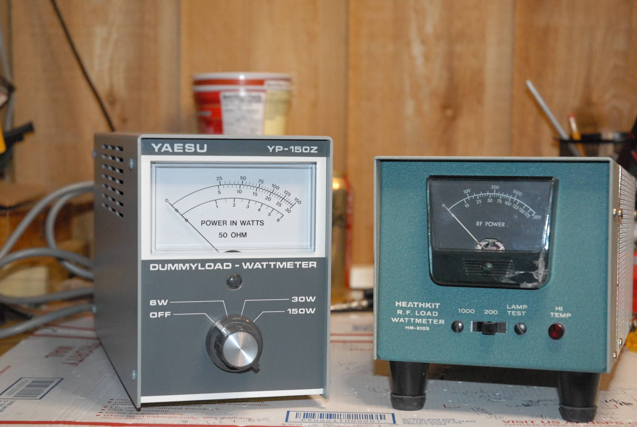
 With the receiver 95+% finished, and the two dummy loads checked and "calibrated" (in quote's 'cuz I'm not NIST), it's time to move on to the SB-401 Transmitter.

I dragged it downstairs, dusted it off, and plopped it on the bench to start the "Forensic Analysis" of it.

Pretty dusty inside, but then the receiver looked this bad when I started, and now it sparkles.

 Missing a couple of screws from the Final Amplifier enclosure lid, but no biggie.

 Removing the chassis from the case and flipping it upside down to inspect the bottom showed no surprises at first look.

I look at everything that's crammed in here, and I'm amazed I built this in eighth-grade.

And it worked, first time! 

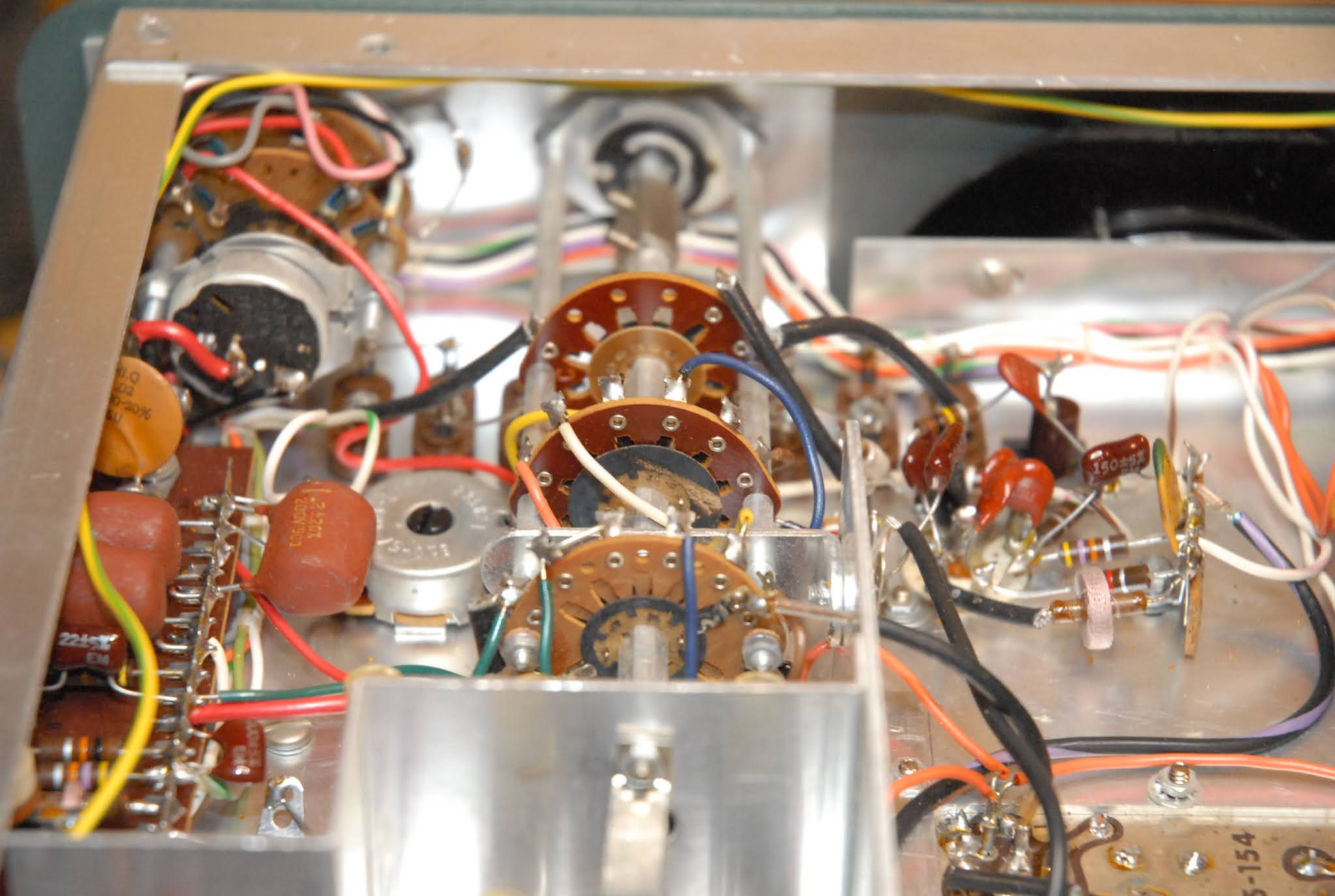
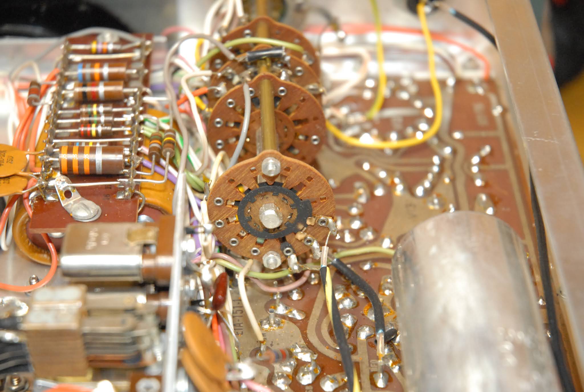
The switch contacts are filthy, as expected, and will need a thorough cleaning and scrubbing.


 If you look closely at the second picture (click to embiggen), you can see what looks like specks of stuff on the very tarnished wafer. I don't know if this "stuff" is just dust, or some kind of crusty corrosion products. Since this radio is undisturbed, I'll get out my loupe and give it a good look.

Tribal Knowledge in the Amateur Radio Community has always held that the black Silver Oxide tarnish is just as conductive as "clean" silver, and to not worry about it on connectors and things.

But what if it's not Silver Oxide? Tarnish on Silver is composed of TWO types of Silver compounds; Silver Oxide, which Tribal Knowledge says is conductive, and Silver Sulfide, which is NOT conductive.

Short of a chemical analysis, which ain't gonna happen, I'll probably never know exactly which type of tarnish I have. And it really doesn't matter as I have a method to restore the switches back to full conductivity.

The inside of the Final Amplifier "cage" shows no signs of overheating or arcing, so that's good.


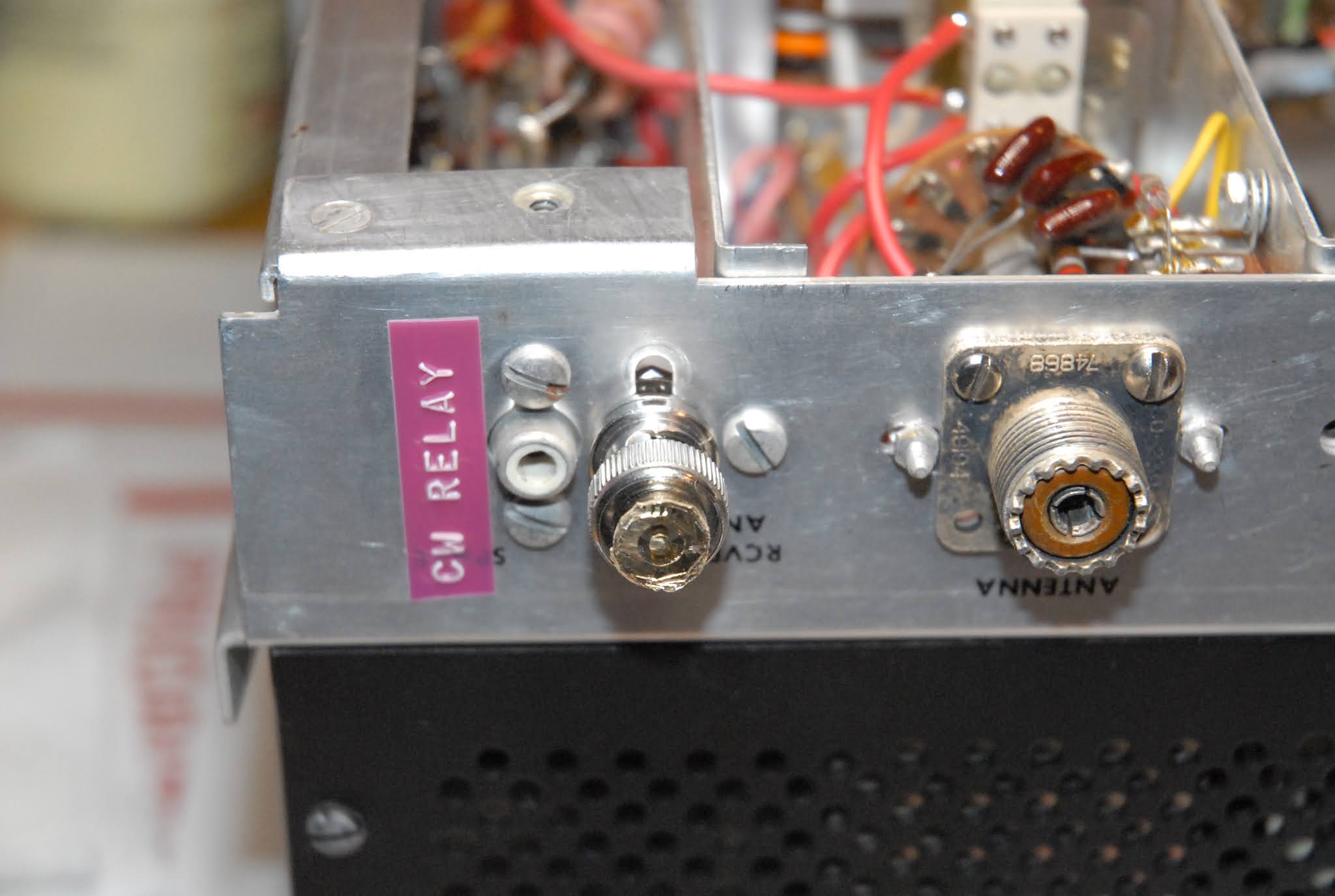
One thing I wanted to check was how tight things were around the ancient "Two Wire" line cord socket. It's a bit cozy down there, but a quick check with a scale shows I have enough room to mount a modern "Three Wire" socket to the chassis, like I did with the receiver.

I also checked the wiring around the rectifiers and filter capacitors, as this area will be getting a complete rework to replace the filter capacitors with new ones, and replace the rectifiers with 20th Century parts. The old "Bullet" rectifiers (the black 'bullets' with the yellow markings) don't have the "surge capacity" of modern ones, so every time you turn on the radio, the current surge to charge the filter capacitors puts a lot of stress on them. Better to replace them now than have one short out, possibly damaging the power transformer.

And that brings us to the only "Surprise!" item I've noticed so far.

The black rectangle in the bottom right of the picture is the power transformer. You can see the brightly colored leads coming out of the black shell of the transformer. Look closely, and you can see what appears to be some shiny stuff that looks like it leaked out.

That's the insulating tar they use in making the transformer, and it shouldn't be there. It's usually a sign that the transformer has been overheated at some point in time, the tar softened up and oozed out, and may or may not be signs of damage. If the radio was overheated due to the operating environment (very hot day in the shack, poor ventilation, running the daylights out of the radio with a high duty-cycle, etc), it might be OK. If it was due to a failing component, like a filter capacitor becoming very leaky, it would usually blow the fuse. There's a whole lotta "If's", "Maybes", and "Could Have Beens" that could cause it to happen. Since I didn't notice this until I pulled the pix off the camera and started writing this post, I can't say if it's a problem.

This is definitely the first thing I'm going to check as soon as I get back in the shop, as if the power transformer is toast (could be why the radios were pulled out of service), I'm going to have some searching to do to get a replacement.

UPDATE:

"Part 2" will address what I find.

After going over the rig again, the stuff that I first thought was tar, is actually the insulating varnish the manufacturer impregnates the assembly with. And boy, did they use a lot!

Before I flipped the rig over to investigate the bottom, I noticed the top of the transformer looked all bumpy with globs of stuff. I put my thumbnail on one of the globs to see how hard it was, and it popped off. It's clear, and very hard. Yep, seen it before and recognize it. Flipped it over, and the same stuff was what I thought was tar. It's very hard, and clear, and I broke a tiny piece off to confirm it.

And the fuse is the correct value, and looks like it's never been out of the holder before.

I'm going to say there was no overheating problem with the transformer (the varnish would have turned dark brown), but rather write it off to jumping to conclusions based on ambiguous evidence.

Heathkit HM-2103 RF Wattmeter / Dummy Load - Part 2 - We're Finished!

 Got my "High Power RF Signal Generator" set up today, and attached it to the Heathkit RF Load.

The little Elecraft K2/100 I have is a pretty stable source for this use. The power control works smoothly to adjust the power from a Watt or two, all the way up to 100 Watts, and is stable. I made up a table of voltage vs power for the range I'd be using, and set things up in CW mode with my foot pedal plugged into the K2. The K2 has a built-in RF Power meter, but I've never properly calibrated it, so I used it to get close to the power level I wanted, and then read the actual RF Voltage it was generating, and then adjust the output power on the K2 to give me the RF Voltage I wanted.

The power formula is P = E^2 / R

If you rearrange things, you get E = sqrtPR

One of these days I'll learn the keystrokes for scientific/mathmatic symbols!


ANYWAY....an easy one to remember is 50 Volts across the load equals 50 Watts of power applied. I made a table with some easy-to-hit numbers, and went from there.

Couldn't take pix of me doing it as that would have required four arms, but it calibrated "As Expected", and it's most likely calibrated better now than it ever was.

All back together and ready to be placed in service!

And I checked the Yaesu YP-150Z Dummy Load / Wattmeter, and it was so close I'll give it a pass. The specs for it are +/- 10%, and with my High Tech Calibration System, it read about half that, or 5%. Since it's "Better Than Advertised", I don't have the heart to break the seals on all three calibration controls inside in some half-a$$ endeavor to "Make It Better".

So tomorrow I'll drag the SB-401 Transmitter downstairs and uncase it for my forensic analysis. Since I'm pretty sure the same guy built both of these radios, I'm bracing myself for more coax replacement, more switch cleaning, more poor soldering and workmanship, and who knows what else.


hey...it keeps me out of the bars at night!


Wednesday, January 20, 2021

Heathkit HM-2103 RF Wattmeter / Dummy Load - Part 1 -

This one item will probably run three parts. It's quite a simple item, and supposedly worked OK. Yep, it's another case of "Ran When Parked".

The first thing to do was pull the covers off as I wanted to check the workmanship, clean it thoroughly, and calibrate it.

OOOPS!

 The large cylindrical shape on the right is the 50 Ohm, 175 Watt load resistor. The angle bracket and white insulator attached to it are not in their correct positions. There should be a 6-32x1/4" machine screw coming up through the slot, and securing the insulator to the chassis. The insulator is molded/cast ceramic with the threads formed in to it. They're somewhat fragile, especially if overtightened, and can easily rip the threads right out of the ceramic. That's what happened here, and the whack that did it might also be responsible for the damage to the meter face, seen in the opening photo.

Bent the bracket up a bit, too.


I bent the bracket straight, pulled the load resistor and cleaned both contact faces on it, and then reassembled the stack using some "Jet Lube SS-30" copper-loaded anti-sieze compound. The SS-30 is about the best stuff I've found for use on RF connections like this, and sections of antenna tubing that telescope together, too. 

This is the "Cold End" (Grounded Side) of the RF Load Resistor giving an idea of how the whole "Load Stack" goes together. There's a 10-32 threaded rod running through the resistor, clamping this end at ground potential.

This is where the resistor mounting plate bolts to the chassis. The instructions specified you sand the paint off the bottom corners of the plate, and also in the center of the plate, as you can see in the above picture.

And down at the other end of the resistor, the now straight bracket and insulator are attached to the chassis with some super strength 3M double sided tape.

 Pretty much back together and ready for calibration.

Ready for calibration, that is, after I do the one repair it needs, replacing the broken capacitor shown here.

If you look carefully, almost in the center of the picture, you'll see a round, yellowish item with what looks to be a chunk taken out of it's center. You'll also see what almost looks like a tiny golf putter sticking out towards the blown-out spot.

Yes, they were one at sometime past. When the Load Resistor got loose and wandered over to the other side of the case, it tore a small ceramic disc capacitor in half. That small capacitor is a 7.7pF, and since it's got one end connector to a source of RF Voltage that can exceed 220 Volts @ 1kW applied power, it should be rated 1kV.

And I don't have any suitable ones in stock. I could cobble something together to make it work, but I'd rather wait for this part to arrive. I'm going to go ahead and calibrate the meter, as that broken part is only selected if you use the "Calibration Using 40 Meters" procedure. Since I'll be calibrating it by measuring the applied RF voltage, I should wind up with a slightly more accurate calibration. Just for grins, though, I'll rerun the calibration using their "40 Meter" method, and see how it comes out compared to measuring the voltage.

Scrounging around the shop reveals no trace (YET!) of my nice, new, fancy RF Voltage probe. The circuit has been around "forever", going back to the 1930's, and these days the packaging's the thing, and this probe just plugs right in any of my nice, new, shiny, calibrated, Digital Multi Meters, and lets me directly read RF voltage up to 250MHz, and 50 Volts applied.

Well, I do have this Old Guy to fall back on.

 A pristine Heathkit RF Probe, Model PK-3, from the late 1960's. And what, pray tell, do I connect such a vintage device to so as to render it useful?

Why, another vintage Test Instrument, what else!

This one's a Heathkit (see a pattern here?) "Model V-6 Vacuum Tube Voltmeter", which was produced from 1952 to 1954. I got this one about six or seven years ago, and promptly rebuilt it. Both tubes were good, but it had a Selenium Rectifier in it, so I replaced that with a silicon diode and a small dropping resistor. I also built a small power supply for the Ohmmeter section, so no more leaky dry cells in the meter. Since I had other meters with current calibration certs, I used them along with some variable power supplies when I calibrated this one. It's pretty dusty from sitting around, so I'll clean it up tomorrow, and start setting up my "High-Power RF Generator" (My Elecraft K2 rig) so I can send some RF into this thing and get it calibrated. Once the Heath wattmeter is finished I'll open the case on the Yaesu meter, clean it, check it, and then calibrate it. It may or may not go on the block. I have three other accurate RF power meters I can use. If I had some vintage Yaesu gear of the same era I'd be tempted to keep it, but I don't.


Monday, January 18, 2021

SB-301 Rebuild Progress - Wrap-Up -

WWV on 15MHz with a few feet of wire. "S-9" signal, and the antenna is several feet below ground level.


 I'm just about to call this one a wrap. As with all the equipment like this I rebuild, I'll let it sit for a couple of days, and then go through it again before I put it back in the case. Sometimes my eye/brain combo needs a rest, and I might just pick up on something I missed the first few times through.

And speaking of things I missed......I forgot to clean the two switches on the front panel while I was busy scrubbing away at the three under the chassis. The "Function" switch was the first one to get cleaned, and then the "AGC" switch. The AGC (Automatic Gain Control) circuit is very important in the radio, as problems in the circuit can make the radio either "deaf" (no gain, or amplification), or overly sensitive (too much gain), which will cause distortion on strong signals. I'd noticed some oddness to the way the AGC circuit was operating, and after I cleaned the switch contacts, I started resoldering the connections to the switch. The first one I went to resolder popped off the terminal as soon as I touched the iron to it! This one wasn't a case of the lead just being stuck through the terminal and soldered. It was just resting on the terminal (like a "Lap Joint"), and was very poorly soldered to it. It looked like the kind of soldered connection that would get you flunked in a soldering class, and between the dirty contacts and bad soldering, was definitely causing problems in the AGC circuit, which now works "As Advertised".

The Function switch also turns on the Crystal Calibrator by grounding the cathode of the tube used in the circuit, and cleaning the contacts on that wafer resulted in the Crystal Calibrator turning on properly when switched into the "CAL" position. 

Cleaning these two switches, and resoldering the connections to them, pretty much cleared up the last few issues I was having with the set behaving oddly, so I ran the calibration procedure again, which went smoothly. I was able to get the dial mechanical zero properly adjusted, and by tuning in WWV on 15MHz, I was able to "Zero Beat" the Crystal Calibrator to WWV, meaning the calibrator is calibrated.

The last thing I did was to run the alignment procedure again, but this time with the Main Tuning set for the middle of the band. Sometimes this allows you to pick up some sensitivity in the section of the band you most frequently operate, and it made a very slight (1/2 S-Unit) improvement.


So, I'll let this sit a day or two, and then move on to the SB-401 Transmitter. Before I tear into the transmitter, though, I'm going to go through these two items:


I have Dummy Loads, and I have Wattmeters. These two are self-contained, and one of those "Handy-To-Have" items. I know the Yaesu one on the left works. I suspect the Heathkit one on the right also works. However, I have no idea of the calibration status of either. Again, I suspect the Yeasu is pretty close, but I have no idea about the Heathkit unit. Since it's a Heathkit, purchased on eBay, it's most prudent to assume it DOESN'T work. The Heath unit requires a 9-Volt battery for the "Hi Temp" warning light, so I have to open it up for that, and I might as well check it and calibrate it. Since I have an accurate RF Probe, it's a simple matter to use one of my transmitters to generate the 100 Watts of RF, which corresponds to 70.7 Volts across the load resistor in these, and then set the calibration controls so the meter reads 100 Watts.

The Yaesu unit is fan-cooled and rated for 150 Watts continuous, and the Heathkit unit is not fan-cooled, but still rated for 175 Watts continuous duty, and 1000 Watts for 4 minutes.


After I've checked/calibrated these units I'll move on to the SB-401 transmitter, which I'm guessing needs as much work as the receiver did.....


Lazy Day.......

 Low 90's today, cloudy and breezy, and we'll probably get an afternoon shower because it's that time of year here. Yes, The Fis...