So, the first thing I did was to get a tour of "Broadway", the passageway that runs from one end of the armored box to the other.
To get down to Broadway, we went down one deck, to the armored hatch that leads down to the third deck:

The beveled edges of the hatch fit in to a matching bevel on the deck:

The door to your left leads into one of the Machine Shops, and is where the table with all the people present on V-J Day in Tokyo Bay stamped their names into the metal table top.
Down through the hatch, on a very steep ladder (the steepest one I've seen so far), and we're "On Broadway".
This is looking forward, with the steep ladder to your left:

And my escort leads the way:

The valves on the left have to do with some of the tanks on the ship, but since my friend is a "Radio Guy" like myself, he wasn't sure exactly what they were for. The red box to the right held a Halon bottle, one of MANY along the sides of the passageway.
This is looking aft of where we were:

The transmitter room is located off Broadway, across from the #2 Engine Room:

I thought I took a picture of the #2 Engine Room, but guess not. Engine Room access is NOT allowed unless you have a very good reason to go there, but sticking my head through the hatch showed another ladder leading WAY down, with lots of steel grating about 8' down, and the reduction gears (so I was told) were visible beneath the grating.
We unlocked the hatch, reached in and turned on the lights, and there it was.....the Transmitter Room:

Each complete transmitter consists of an exciter (puts out about 10 Watts), with a power amplifier beneath it (runs 1000 Watts output forever), and a power supply for the exciter on the bottom. These are nominally used for 2~30 MHz operation, the exciters are manually tuned, and generally get their audio/data input from "Radio Central", which is where we operate the Amateur radio station from. The exciters also have a jack for a push-to-talk handset, and a CW (Morse Code) key on the front panel, although my escort, who served on the USS Wisconsin, says he doesn't remember them ever using CW.

Across from each transmitter is the Antenna Coupler. From the writing and Dymo label (remember Dymo labels?) this coupler is for the 2~6MHz range, and connected to the "Twin Fan" antenna. The Twin Fan antenna disappeared at sometime during the Iowa's stay at Suisun Bay, and we're working on getting it replaced. Strangely enough, all of the parts to rebuild it are readily available, but he cost is something like $25,000, which is money we just don't have. The guys on the New Jersey, BB-62, have been most generous with sending us spares for just the cost of shipping, and while they have some spares for the Twin Fan antenna, wed still be out-of-pocket quite a bit of money to replace the antenna with a exact duplicate. We might just scratch our heads a bit to see if we can come up with something that looks the same, and functions the same, but for a lot less cost.
These are what you see in the picture looking in to the Transmitter Room, all located to your right:

To connect one of the transmitter/coupler pairs to a particular antenna, or a dummy load, these patch bays are used:

There's a special "Break Out" or Patch cable used that has a large, rectangular box on one end that slips into the rectangular black sockets, and then connects to the Type-N RF connector, and "Amphenol" connector in the center of the panel:

Here's one of the dry Dummy Loads sitting by the hatch leading in to the Transmitter Room:

Off to one side, is this "stand alone" transmitter unit. The additional box on the top with the two round meters is an antenna auto-coupler. We still have to trace out the cabling for this unit to see where it goes. I found one whip antenna with the remote coupling unit mounted at its base the other day, and it's possible that this transmitter is connected to it. Until we look at the wire number tags on this unit, and the coupler at the base of the antenna, it's a mystery where this one is connected to, and what it's use was:

Further down the row, on the side where the Antenna Couplers are, are these WSC-3, "Whiskey-3", UHF radios, used for SatCom:

And between the racks of WSC-3 radios is this rack containing what appears to be an Antenna Coupler for them:

I know next to nothing about these radios, and as it's highly unlikely we'd ever get a license to use them, they're probably just going to quietly sit there for a long, long time.
Back on the other side of the room are some radios and amplifiers I've actually owned in the distant, dusty past, the famous AN/ART-21 and AN/GRR-23(V), along with the AM-6153 RF Power Amplifier.
The AM-6154 amp was quite popular 'back in the day' to convert to 2 Meter Amateur radio operation. Fair Radio Sales used to have truckloads of them, but these days they command a very high price.
These radios were used to communicate with aircraft in the VHF Aircraft Band.
This is the entire rack, from top to bottom:


One very interesting radio set I found was a"Green Radio" like the ground forces use(d), the RT-524A.
I'm guessing this radio was used to communicate with our ground forces who requested Naval Gunfire Support:

Power Supply:

And a complete set, the second one in this rack:

These appear to be some type of coupler/tuning unit/SWR bridge, and since they're green, and located next to the RT-524's, I'm guessing they're part of that system:

And since we'll be working on the HF transmitters, here's a shot of where the circuit breakers for all the HF Transmitters are located:

One of my tasks as "Lead Technician" for getting the HF transmitters going again (don't ask me how I was chosen as 'lead tech', as I'm clueless!) is to photo document where things are, and the process used to get these big guys going again, so this is just a start of the many pictures I'll be taking as I spend more time down there. The guys on the New Jersey and Missouri loaned us the Technical Manuals, which we had photocopied and then returned, so we have fairly complete documentation. HOWEVER....I'm told each one of the Iowa class ships wound up a bit different, so just because we have the TM's for the equipment doesn't mean we're out of the woods!
On our way back out, I took a few more pictures of the 1930's technology that made the ship operate.
Looking down Broadway:

I think the grey hose is left from when she was in storage, as I know there are many others like this in some of the "off limits" areas, and look just like it.
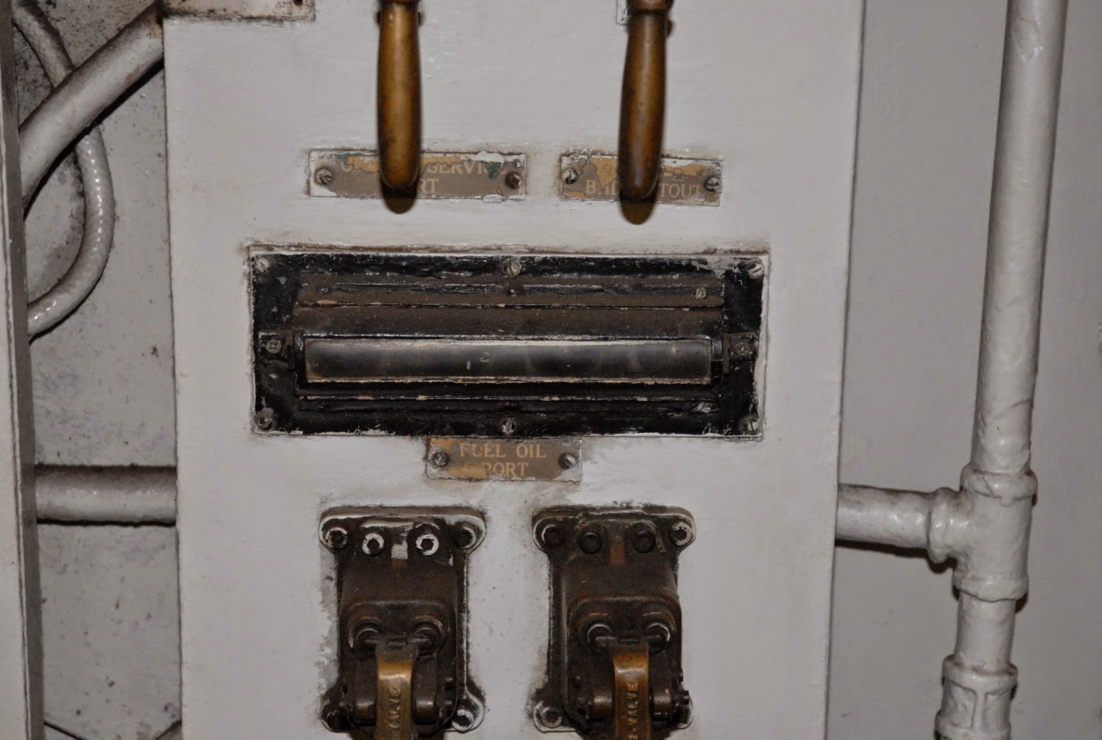
Some valves used to control "Flooding The Wing Tanks":

A close-up for any Steampunkers out there:

More valves:

Close-up:
I spent about three hours down in the Transmitter Room, and we went through all of the filing and storage cabinets. We found lots of patch cables, boxes full of spare modules, a lot of miscellaneous JUNQUE, and a bunch of spare 8122 ceramic power tubes, condition unknown.
After spending the time down below, I went up to where I normally hangout, and helped a retired PhD from MIT troubleshoot one of the URR-74(V)2 Watkins-Johnson LF/MF/HF receivers.
We have three of these receivers, and only one operates correctly. The other two seem "deaf", so we're starting at the antenna using KNX 1070 for a test signal, and tracing the signal out.
Looks like there's a problem in the "A3 Module", which is the front-end of the receiver with the 1st and 2nd mixer and IF stages in it.
.....Sigh......So much for being "retired"!


It does this old sailor's heart good, to see all that old school tech - even older than the 1944 destroyer I lived on. :)
ReplyDeleteYeah, and it uses TOOOBS!!
ReplyDeleteEven some of the receivers have tube front ends.
FYI, Whiskey 3s are STILL in use... and the 'green' radios are FM for the Army.
ReplyDeleteOh, I know exactly what the Green Radios are. One of my friends has a couple, along with a truckload of other Green Radios.
DeleteI was just surprised to see them, but then since the Iowa did support of ground forces, I shouldn't have been!
Reblogged on Musings of the Desert Rat.
ReplyDeleteThanks so much for sharing the story and those amazing pics, I definitely had a Tim the Tool Man moment there! :-)
You're very welcome, Mark.
DeleteI've just got started on this project, and while these radios would be somewhat cumbersome to use for Ham Radio, when (not if!) we get these going again, we'll be only the second Iowa-class ship with some original gear on the air.
E-Mail me at dwetherill@gmail if you would like some troubleshooting tips on the T-827, the exciter for the AN/URT-23. I had 12 of them on the John F. Kennedy (CV-67) and may be able to help.
ReplyDeleteThanks, I'll get in touch with you.
DeleteI just made a new post about getting one of them back in service. We still have some more testing to do before we can connect it to an antenna, but we're making progress!
The AN/WSC-3 radio is limited to 225 - 399.75 MHz, so no, you would not get a chance to use them on the ham bands. There were about fifteen variants of the WSC-3 designed, about half of them actually manufactured and placed in service. Some are optimized for data, some for voice and some for SATCOMM. No one WSC-3 does it all.
ReplyDeleteThat is a coupler between the stacks of WSC-3 radios. I recall the nomenclature as OA-9277 and it allowed for 4 radios to use one antenna. Freqs needed to be separated by 5 MHz -- not usually a problem. It's predecessor, the SRA-33 did the same thing but did not have push-button frequency entry; it had clickety-click switches, some of which were known for breakety-breaking.
The exciter for the URT-23 is the T-827, which nominally put out 100W. The amp kicked it up to a KW, but the ET's usually rigged the power meter so it indicated the KW when it was actually putting out less. They lasted longer that way and could still be heard nicely at the distant end with an actual 850W, less than half an S-unit down.
I spent about a decade of my second career doing shipboard EMI inspections after I retired from the Navy in 1982. I was heavy into antennas and assorted topside material but spent plenty of time in the Comm spaces along the way.
John, KD6VKW, San Diego-area
Thanks for the info, John!
ReplyDeleteThese exciters only put out 100mW, and the finals are good for about 1250 Watts.
Due to RF exposure limits to the public (the "uncontrolled" area), we have to stay under 250 Watts, and under 28MHz.
That gives us a few feet of extra margin so we don't have to move the tour route so it bypasses the area where the antennas are located.
We have to original "steerable" antennas for the Whiskey 3's, but no controller for them.
We recently received 4 of the "eggbeater" omnidirectional antennas for them, and have them mounted, but they're just for looks. We lack, and can't find, the downconverter boxes that get mounted at the omni antennas.